Motion in Two and Three Dimensions
Objectives
In this chapter we will study motion in a plane (two dimensions) and motion in space (three dimensions):
The following vectors will be defined for two- and three- dimensional motion:
Position and Displacement
Average and Instantaneous velocity
Average and instantaneous acceleration
We will consider in detail projectile motion and uniform circular motion as examples of two dimensional motion.
Finally we will consider relative motion, i.e. the transformation of velocities between two reference systems which move with respect to each other with constant velocity.
Position
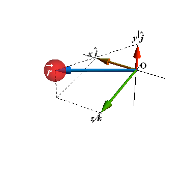
In three dimensional space, a particle is located by a position vector ![]() .
.
Vector ![]() extends from a reference point (origin of a coordinate system) to the particle.
extends from a reference point (origin of a coordinate system) to the particle.

In three dimension ![]() has three components and in unit vector notation
has three components and in unit vector notation ![]() is written as
is written as
![]()
x, y and z are three components of the position vector ![]() .
.
Displacement
Watch the motion of three disks from initial position ![]() (click play).
(click play).
All the three disks moved (displaced) through different paths to a final position ![]() .
.
How displacement is computed?
Displacement is computed by subtracting initial position ![]() from final position
from final position ![]() .
.
![]()
Although all the three disks (red, blue and green) starting from same initial position ![]() follow different paths to reach the final position
follow different paths to reach the final position ![]() , but all three paths connecting the two points correspond to the same displacement vector
, but all three paths connecting the two points correspond to the same displacement vector ![]()
Displacement vector is drawn as an arrow (purple arrow) connecting the initial point with final point with its arrowhead at final position
In unit vector notation, displacement vector ![]() is computed as
is computed as
![]()
We can also rewrite displacement vector ![]() by substituting
by substituting ![]() ,
, ![]() and
and ![]()
![]()
Average Velocity
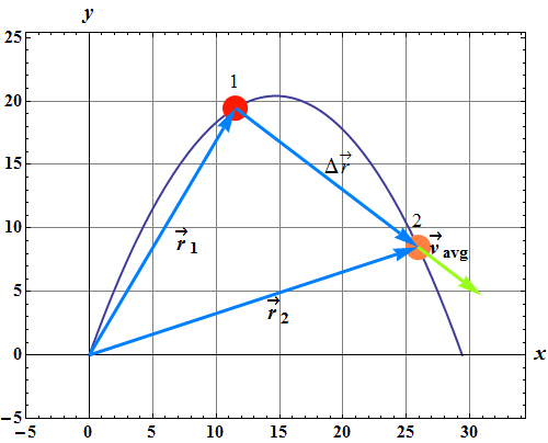
When a particle moves from a position ![]() to
to ![]() in time interval Δt, the average velocity
in time interval Δt, the average velocity ![]() is given as
is given as

Average velocity ![]() in terms of component is written as
in terms of component is written as


Direction of average velocity vector ![]() (green arrow) is always along the displacement vector
(green arrow) is always along the displacement vector ![]() as shown in above figure.
as shown in above figure.
Instantaneous Velocity
Instantaneous velocity ![]() is the velocity at some instant.
is the velocity at some instant.
When we shrink the value of time interval Δ t such that Δt→0, average velocity ![]() approaches to instantaneous velocity
approaches to instantaneous velocity ![]() .
.
(reduce the time interval Δt and watch)

In unit vector form
![]()
where

What will be the direction of instantaneous velocity?
Let us try to reduce the value of Δ t in the following 2D simulation by sliding the Δt bar towards left hand side.
Red line passing through initial position (1) of the particle is the tangent to the trajectory (path) of the particle.
What we observed?
When the value of Δ t→0, the ![]() becomes
becomes ![]() and its direction is along the tangent to the trajectory at the particle position at that instant.
and its direction is along the tangent to the trajectory at the particle position at that instant.
Press the play button in the following simulation and observe how the direction of velocity vector ![]() changes as the particle moves along the trajectory.
changes as the particle moves along the trajectory.
The direction of instantaneous velocity ![]() of a moving particle at any point on the path of the particle is always along the tangent (red line) to the path (trajectory) at that point or position.
of a moving particle at any point on the path of the particle is always along the tangent (red line) to the path (trajectory) at that point or position.
Checkpoint - 1
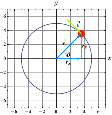
Following figure shows a circular path taken by a particle. Instantaneous velocity of the particle is given in the figure.
For given velocity, through which quadrant is the particle moving at that instant if it is traveling (a) clockwise and (b) counterclockwise around the circle? For both cases, draw ![]() on the figure.
on the figure.
Draw the velocity vector. (Click, hold and drag the velocity vector to any location)
To bring it back to center, click at the center.
Hint: The direction of instantaneous velocity ![]() of a moving particle at any point on the path of the particle is always along the tangent to the path at that point or position.
of a moving particle at any point on the path of the particle is always along the tangent to the path at that point or position.
Move the velocity vector and find out at which point velocity vector is along the tangent to the circle?
Average Acceleration and Instantaneous Acceleration
When a velocity of a particle changes from ![]() to
to ![]() in time interval Δt, the average acceleration
in time interval Δt, the average acceleration ![]() is given as
is given as

Average acceleration ![]() in terms of component is written as
in terms of component is written as

When we shrink the value of Δ t to zero, the ![]() becomes instantaneous acceleration (or acceleration)
becomes instantaneous acceleration (or acceleration) ![]() at that instant.
at that instant.

In unit vector form
![]()
where

Relation between direction of velocity and acceleration
Watch the motion of red disk (click play).
We can observe that the velocity vector (green) and acceleration vector (orange) change with time.
Red line is tangent to the trajectory and blue arrow is position vector.
What we observed?
![]() is always along the tangent line (red) to the trajectory at that instant.
is always along the tangent line (red) to the trajectory at that instant.
At the turning point observe, ![]() and
and ![]() are at right angle to each other.
are at right angle to each other.
Projectile Motion
What is a projectile?
Any motion satisfying following two conditions is called projectile motion.
When an object moves ONLY under the influence of acceleration due to gravity g.
![]()
Its initial velocity ![]() must have a finite horizontal component
must have a finite horizontal component ![]() .
.
![]()
where
![]()
Click the play button and observe the trajectory of projectile motion.
How velocity components change as the particle move?
Horizontal component remained constant.
Vertical component changed.
In projectile motion, the horizontal motion and the vertical motion are independent of each other; means neither motion affects the other.
Projectile Motion Analyzed
The Horizontal Displacement
In case of a projectile motion, horizontal component of acceleration ![]() , therefore horizontal displacement
, therefore horizontal displacement
![]()
The Vertical Displacement
In case of a projectile motion, vertical component of acceleration ![]() , therefore vertical displacement
, therefore vertical displacement

The Horizontal Range
The horizontal range ![]() of the projectile is the horizontal distance the projectile has traveled when it returns to its initial (launch) height or when
of the projectile is the horizontal distance the projectile has traveled when it returns to its initial (launch) height or when ![]() .
.
How to compute range?
Range is the horizontal displacement in the time "t" when object comes back to its original Vertical position or vertical displacement becomes zero.

Once we know time "t", we get range R as below.
![]()
Eliminating t, from above two equations yields

Using trigonometric identity sin 2θ=2sinθ cosθ, we get

Horizontal range R will be maximum when sin 2θ=1, or ![]()
In the following simulation play and change the angle.
Find out at what angle is the range maximum?
The horizontal range R is maximum for a launch angle of ![]() .
.
Checkpoint 2
In the above projectile simulation observe the direction of velocity components as it moves.
How ![]() and
and ![]() behave?
behave?
Suppose at a certain instant, a fly ball has velocity ![]() (the x axis is horizontal, the y axis is upward, and
(the x axis is horizontal, the y axis is upward, and ![]() is in meters per second).
is in meters per second).
Has the ball passed its highest point?
Uniform Circular Motion
A particle moving with constant speed v in a circular path is said to be in uniform circular motion. (See the following simulation.)
Is velocity ![]() constant or changing?
constant or changing?
Is magnitude of velocity (speed) ![]() constant or changing?
constant or changing?
Time Period
The period of revolution T is given as

where r is the radius of the circle and v is the speed (magnitude of velocity) of the rotating object.
The position vector of a particle moving around a circle or a circular arc at constant (uniform) speed is given as

![]()
θ is a function of time and its value is 2π in one period of revolution T, so θ(t) can be written as

By substituting value of T we get

By substituting value of θ(t), the position vector can be written as
![]()
Velocity and acceleration can be computed as


Magnitude of ![]() is found to be
is found to be

We know that
![]()
Therefore

What is the direction of ![]() ?
?
In circular motion, acceleration ![]() always points radially inward.
always points radially inward.
This radially inward acceleration associated with uniform circular motion is called a centripetal (meaning “center seeking”) acceleration.
Checkpoint 3
An object moves at constant speed along a circular path in a horizontal xy plane, with the center at the origin. When the object is at x=-2m, its velocity is ![]() . Give the object’s (a) velocity and (b) acceleration at y=-2m.
. Give the object’s (a) velocity and (b) acceleration at y=-2m.
Relative Motion in One Dimension
When two cars are moving side by side with same velocity, for the drivers of each car, the other car is stationary while for an observer on the road, both cars are moving.
In other words, the velocity of a particle depends on the reference frame of observer measuring the velocity.
Consider two frames A and B with a red disk moving in Frame B.
When Frame A and Frame B both are stationary, the observer in frame A and another observer in frame B measure the position of red disk P (Click Play to move disk P).
Here position measured by both the observers will be same.
![]()
Suppose Frame B is moving with constant velocity ![]() in stationary frame A. (Reset, select Frame B moving and click Play).
in stationary frame A. (Reset, select Frame B moving and click Play).
Now the relation between the positions measured by two observers at any instant will be given as
![]()
Where ![]() and
and ![]() are the positions of particle measure by observer in frame A and in frame B respectively,
are the positions of particle measure by observer in frame A and in frame B respectively, ![]() is the position of B measured by observer in frame A.
is the position of B measured by observer in frame A.
Relation between the velocities can be given as

![]()
If frame B is moving with a constant velocity, the relation between acceleration is given as.

Because ![]() is constant, therefore its derivative is
is constant, therefore its derivative is ![]() .
.
![]()
Observers on different frames of reference that move at constant velocity relative to each other will measure the same acceleration for a moving particle.
Relative Motion in Two Dimensions
In two dimensions suppose a particle P is moving in frame B and frame B is moving with velocity ![]() with respect to frame A (Click Reset and then play).
with respect to frame A (Click Reset and then play).
The relation between the position measurements of particle P by observer in frame A (![]() ) and by an observer in frame B (
) and by an observer in frame B (![]() ) will be given as
) will be given as
![]()
Where ![]() and
and ![]() are the positions of particle measure by observer in frame A and frame B respectively,
are the positions of particle measure by observer in frame A and frame B respectively, ![]() is the position of origin of frame B from origin of frame A.
is the position of origin of frame B from origin of frame A.
![]()
Relation between the velocities can be given as

![]()
Similarly the relation between acceleration is given as.

![]()
If frame B is moving with a constant velocity ![]() , its derivative will be zero therefore
, its derivative will be zero therefore ![]() .
.
![]()
