Interference
The concept of optical interference is critical to understand many natural phenomena, ranging from color shifting in butterfly wings to intensity patterns formed by small apertures.
These phenomena cannot be explained using simple geometrical optics, and are based on the wave nature of light.
Objectives
In this chapter we will learn following topics using the wave nature of light.
Huygens' principle
Derivation of law of refraction using Huygens' principle.
How index of refraction is related to the speed of light?
Why wavelength of light changes as it travel in different medium?
What is interference?
Why an interference pattern is generated by two light beams?
Young's Interference Experiment.
Light as a Wave
We know that light is an electromagnetic wave.
When an oscillating or accelerating charge generates changing electric and magnetic fields, the electromagnetic wave propagates like expanding spheres.
Surface of these expanding spheres is called wave front.
A cross section of this wave propagation is shown in the simulation.
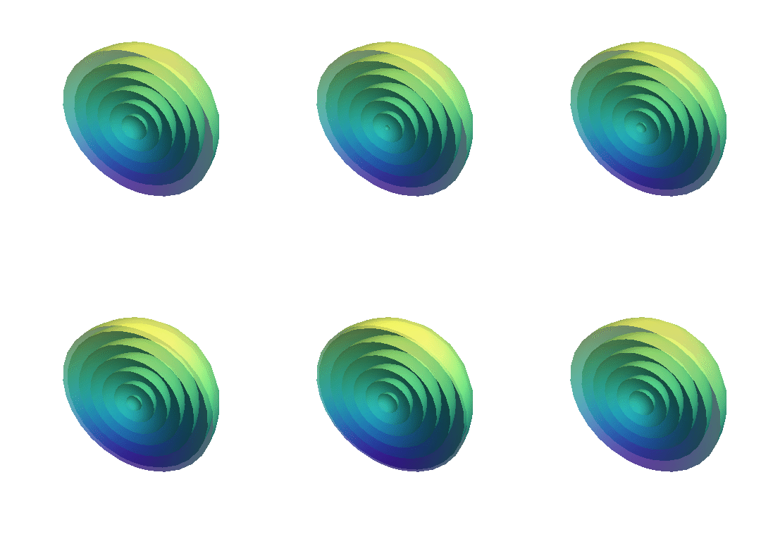
If we look at the propagating light wave or electromagnetic wave from the top, it will look some thing like in the following simulation.
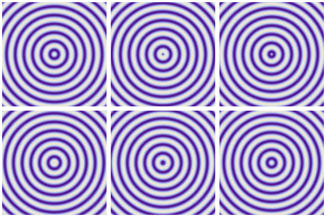
Bright regions corresponds to finite energy (Electric field ![]() is non zero therefore electric field energy density
is non zero therefore electric field energy density ![]() is not zero) and dark regions correspond to no energy.
is not zero) and dark regions correspond to no energy.
Propagation of wave means flow of energy from the generation point to surroundings in the space.
If we look at the variation of electric field and field energy along a line joining central point to any point in the space, it will be as shown in following simulation.
Huygens' principle
Huygens was the first (1678) person to advance a convincing wave theory for light.
It is not as comprehensive as the electromagnetic theory.
It is simple mathematically and is based on geometrical construction.
Any extended object can be considered as made up of several point sources.
As we have seen that each point source generates a wavefront and sum of these wavefront creates an extended wavefront.
According to Huygens' principle.
All points on a wavefront serve as point sources of spherical secondary wavelets. After a time t, the new position of the wavefront will be that of a surface tangent to these secondary wavelets.
Law of Refraction (Using Huygens' principle)
Consider a wavefronts of light, moving with speed ![]() in air and making an angle
in air and making an angle ![]() with the surface of a glass plate.
with the surface of a glass plate.
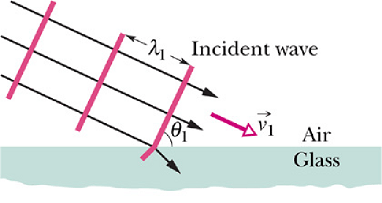
![]() has same value as the angle between the normal to the wavefront and normal to the surface.
has same value as the angle between the normal to the wavefront and normal to the surface.
Or ![]() is the angle of incidence.
is the angle of incidence.
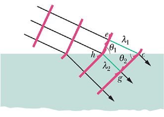
Suppose that the Huygens' wavelet at point e expand to pass through point c at a distance ![]() , from point e. Time t taken in covering this distance will be
, from point e. Time t taken in covering this distance will be

Suppose in same time t, a wavelet starting at point h reaches to point g at distance ![]() in glass. If
in glass. If ![]() is the speed of light in glass, then
is the speed of light in glass, then

By equating these two equations we get

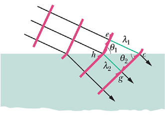
In the above figure.

and

By taking the ratio of above two equations we get

If we define index of refraction n for each medium as
![]()
For our two media we get
![]()
By substituting these values in sinθ equation we get

Or
![]()
Checkpoint 1
The figure shows a monochromatic ray of light traveling across parallel interfaces, from an original material a, through layers of materials b and c, and then back into material a. Rank the materials according to the speed of light in them, greatest first.
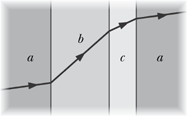
Hint : If speed is smaller, angle θ is smaller.
Wavelength and index of refraction
What is primary, wavelength or frequency?
As we know the electromagnetic wave is produced by oscillating charges.
If f is the frequency of the oscillating charge, then f will be the frequency of the wave.
We can say that frequency of the light wave was decided by the oscillating charge which produced it, therefore frequency got decided at the birth of the wave and is primary for a wave.
Relation between index of refraction and wavelength.
Now if v is the speed of the wave in a medium (speed is a property of the medium), the wavelength λ is given as

As we have seen the speed of light in a medium of refractive index n is v=c/n, therefore

If ![]() is the wavelength of the light wave in vacuum, then
is the wavelength of the light wave in vacuum, then

The wavelength λ of the light in a medium of refractive index n can be written in terms of the wavelength in vacuum ![]() as
as

The fact that the wavelength of light depends on the index of refraction is important in certain situations involving the interference of light waves.
Relation of Phase change to Refractive index.
For a sinusoidal wave the field amplitude at any time t and position r is given as,
![]()
Or

The term  is called phase of the wave and φ is initial phase.
Suppose a light wave pass through two mediums of same length with different index of refraction.
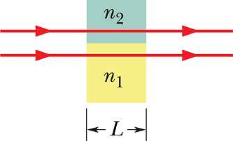
At the exit of the wave from the two medium, the phase values of the wave will be different and are given as

and

In medium 1

Where ![]() is the wavelength in vacuum.
is the wavelength in vacuum.
And in medium 2

Term ![]() is equal to the number of wavelengths that fits in medium of length L.
is equal to the number of wavelengths that fits in medium of length L.
Therefore the phase difference Δφ will be

Checkpoint 2
The light waves of the rays in the figure have the same wavelength and amplitude and are initially in phase. (a) If 7.60 wavelengths fit within the length of the top material and 5.50 wavelengths fit within that of the bottom material, which material has the greater index of refraction? (b) If the rays are angled slightly so that they meet at the same point on a distant screen, will the interference there result in the brightest possible illumination, bright intermediate illumination, dark intermediate illumination, or darkness?
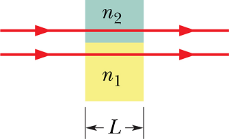
Hint : (a) ![]() , (b) One wavelength difference cause a phase difference of 2π.
, (b) One wavelength difference cause a phase difference of 2π.
Interference
We have seen that a single oscillating source radiates electromagnetic waves in space.
What happens when we have two sources ![]() sitting side by side a few centimeter apart (assume that both the sources are driven by same LC-circuit and have same frequency)?
sitting side by side a few centimeter apart (assume that both the sources are driven by same LC-circuit and have same frequency)?
According to law of superposition, the net electric (magnetic) field at any point in space should be the vector sum of the individual electric (magnetic) fields.
Result is shown in following simulation.
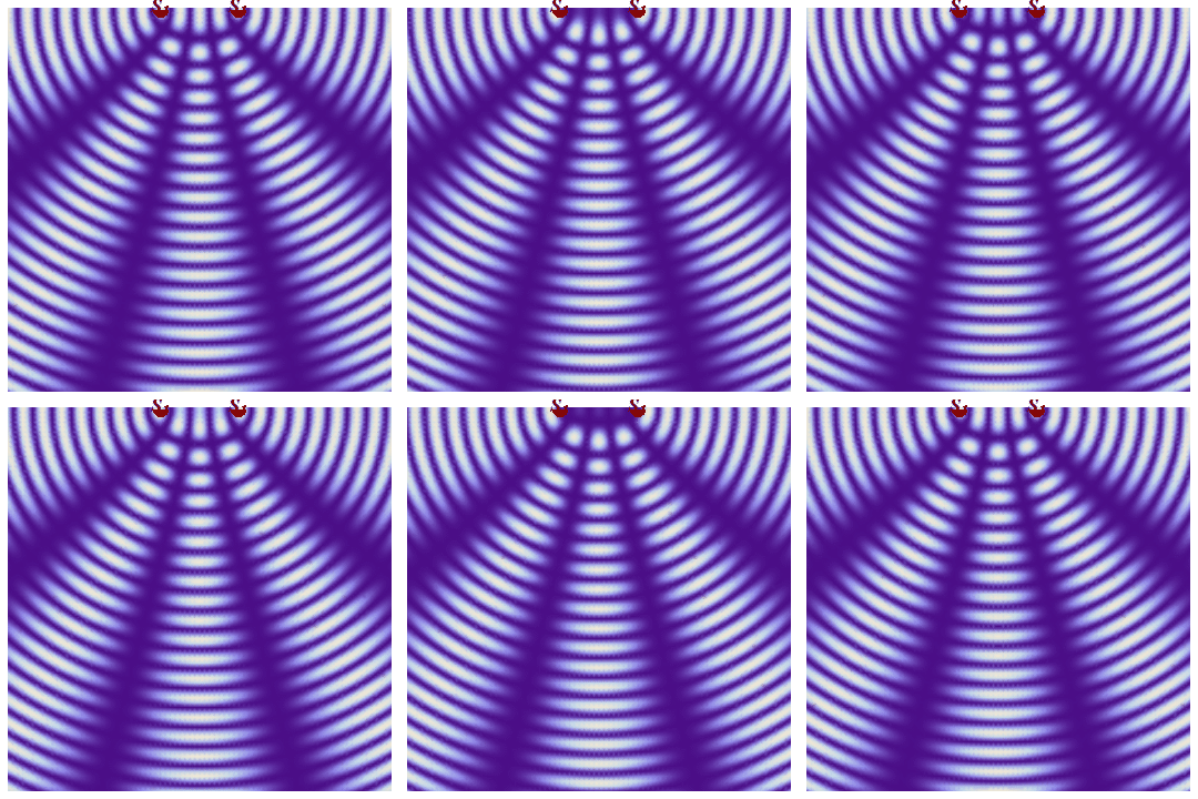
This phenomenon of superposition of waves from two sources is called interference.
Coherence
In the last simulation we made an assumption that both the sources are driven by same LC-circuit and have same frequency.
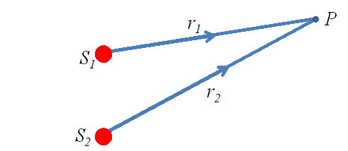
That means electric fields at any time t, at a point P in space radiated by the two sources ![]() and
and ![]() will be given as
will be given as
![]()
and
![]()
The phase difference of these two field at any point in space does not vary in time.
![]()
Any two light (electromagnetic) waves whose phase difference does not vary with time are called coherent waves.
Interference produced by coherent waves is stable in time.
If electromagnetic wave generators synchronously oscillate with same frequency, they will be called coherent sources.
Laser light source is an example of coherent light source. All the atoms/molecules in a laser source emits light (electromagnetic wave) cooperatively at same frequency.
Light produced by an electric bulb is an example of incoherent light source as all the atoms in its filament emit light in a random fashion, independent of each other.
Young's Interference Experiment
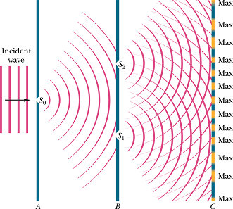
In 1801, Thomas Young did the following experiment and found that light produces fringes on the screen.
 |
 |
In case of radio wave or microwave we can produce two coherent sources by connecting two antennas with same generator(LC circuit).
Here in Young's experiment, light was obtained from a single source and then split into two sources as shown in figure.
This makes the two sources coherent as they are originating from the same source.
The interference of these two sources generates bright and dark bands (fringes) on the screen.
What causes Interference?
We have seen that phase difference between two waves can change if the waves travel paths of different lengths.
If the phase difference Δφ at a point P is such that the electric fields due to two sources adds up to zero, energy density ![]() will be zero at that.
will be zero at that.
If the phase difference Δφ at a point P is such that the electric fields due to two sources is the sum of two magnitudes, the energy density ![]() will be maximum at that.
will be maximum at that.
Let us see how the energy density due to two coherent sources, changes with the phase difference at a point in space.
We have seen that interference patterns are generated by phase difference in two waves at a point.
Math of Interference.
Consider the setup shown in Young's Experiment.
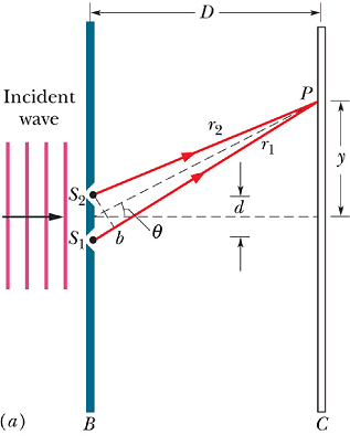
The electric fields at any time t, at a point P in space radiated by the two sources ![]() and
and ![]() will be given as
will be given as
![]()
and
![]()
Here we are assuming that amplitude of both the wave is same ![]() and initial phase φ=0.
and initial phase φ=0.
The net electric field E at point P will be given as
![]()
For convenience we can write
![]()
where
![]()
In our trigonometric class we may have learned

By substituting this, the value of electric field turn out to be

It is an oscillating electric field with magnitude ![]() as
as

Let us calculate ![]() .
.

Consider an observation point making angle θ with an axis passing through the middle of two sources ![]() and
and ![]() .
.
Lat us assume ![]() and
and ![]() . In other words, position of P is very large in comparison to the distance d between two sources.
. In other words, position of P is very large in comparison to the distance d between two sources.
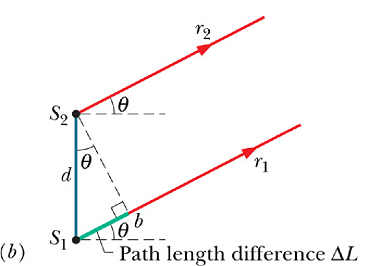
With above assumption, ![]() and
and ![]() can be taken as parallel. Path difference
can be taken as parallel. Path difference ![]() can be given as
can be given as
![]()
Path difference will be

Electric field magnitude ![]() can be written as
can be written as
![]()
Now ![]() will be maximum (bright fringe) when ever
will be maximum (bright fringe) when ever
![]()
Or
![]()
Similarly, ![]() will be minimum (dark fringe) when ever
will be minimum (dark fringe) when ever

Or

