Induction and Inductance
Objectives
Faraday’s law of induction
Lenz’s rule
Induction and Energy Transfer
Electric field induced by a changing magnetic field
Inductance and mutual inductance
RL circuits
Energy stored in a magnetic field
Faraday's law of Induction
Experiment - 1
Let us do a simulation experiment based on the experiments done by Michael Faraday and Joseph Henry.
Consider a conducting wire loop connected to a sensitive Ammeter (or Galvanometer). There is no battery in the circuit, current in the loop should be zero.
Observe the ammeter and see what happens when we move a magnet towards the loop?
Now move the magnet back and again observe the ammeter.
Increase the speed of magnet movement from 0.5 to 1 and repeat the experiment.
Reverse the polarity of the magnet and repeat the experiment.
What were our observations?
Movement of a magnet produces current in the loop.
Faster motion produces a greater current.
If moving the magnet's north pole toward the loop causes, say, clockwise current, then moving the north pole away causes counterclockwise current.
Moving the south pole toward or away from the loop also causes currents, but in the reversed directions.
What is the conclusion?
Current appears in the loop, only if there is relative motion between the loop and the magnet (one must move relative to the other); the current disappears when the relative motion between them ceases.
Such a current produced in the loop is called an "induced current".
The emf producing this induced current is called an induced emf ( Work done per unit charge to produce that current).
The process of producing the current and emf is called induction.
Experiment - 2
Let us conduct an other experiment. Consider two conducting loops as shown in the simulation figure.(for proper working first select 1 for Ammeter testing)
An ammeter is connected in one of the loop but no battery is there to produce current in that loop.
An emf source (battery) is connected in the second loop with an open switch.
Let us close the switch of second loop and observe the ammeter in first loop.
Now again open the switch of second loop and observe the ammeter in first loop.
What were our observations?
If we close switch S, to turn on a current in the right-hand loop, the meter suddenly and briefly registers a current—an induced current—in the left-hand loop.
When we open the switch, another sudden and brief induced current appears in the left-hand loop, but in the opposite direction.
What is the conclusion?
We get an induced current (and thus an induced emf) only when the current in the right-hand loop is changing (either turning on or turning off) and not when it is constant (even if current is large).
Summary of these Experiments :
Faraday summarized the results of these experiments in what is known as Faraday's law of Induction.
An emf is induced in a loop when the magnitude or strength of magnetic field that pass through the loop is changing.
Faraday equated the “amount of magnetic field” in terms of the magnetic field lines passing through the loop. Now the Faraday' s law of induction, can also be stated as:
An emf is induced in a loop when the number of magnetic field lines that pass through the loop is changing.
Faraday' s law is not an explanation of Induction but merely a description of what induction is.
A Quantitative Treatment
Magnetic field Flux ![]() .
.
First we need to define a quantity called Magnetic field flux ![]() .
.
We are well aware of the electric field flux ![]() of an electric field
of an electric field ![]() passing through a loop of surface are
passing through a loop of surface are ![]() . It is defined as
. It is defined as

In a similar fashion the magnetic field flux ![]() through a loop of area
through a loop of area ![]() , placed in a magnetic field
, placed in a magnetic field ![]() is defined as
is defined as

Or

Where φ is the angle between magnetic field ![]() and area vector
and area vector ![]() .
.

When ![]() is uniform and area vector
is uniform and area vector ![]() of the loop is parallel to the magnetic field
of the loop is parallel to the magnetic field ![]() , the magnetic flux
, the magnetic flux ![]() through the loop is simply given as
through the loop is simply given as
![]()
SI unit for magnetic flux is the Tesla - square meter, which is called the Weber (abbreviated Wb) :
![]()
Faraday's law can be restated in quantitative form as
The magnitude of the emf E induced in a conducting loop is equal to the rate at which the magnetic flux ![]() changes through that loop with time.
changes through that loop with time.

Will will learn about the negative sign in front of ![]() in the next section.
in the next section.
Induced emf in a coil :
If there are N turns in a coil, the change in magnetic flux through the coil will induce emf in each turns.
The total emf induced in the coil will be the sum of these individual induced emfs.

Here we are assuming that the coil is tightly wound (closely packed), so that the same magnetic flux passes through all the turns.
Checkpoint 1
The graph gives the magnitude B(t) of a uniform magnetic field that exists throughout a conducting loop, with the direction of the field perpendicular to the plane of the loop. Rank the five regions of the graph according to the magnitude of the emf induced in the loop, greatest first.

Hint : ![]() is equal to the slope of the line in above graph.
is equal to the slope of the line in above graph.
Method's of Changing Magnetic flux through a loop:
Change the magnitude B of the magnetic field within the coil.
Change the angle between the direction of the magnetic field and the plane of the coil (for example, by rotating the coil so that field is first perpendicular to the plane of the coil and then is along that plane).
Change the total area of the coil or the portion of that area that lies within the magnetic field (for example, by expanding the coil or sliding it into or out of the field).
Problem/Demonstration :
A rectangular coil of N turns and of length a and width b is rotated at frequency f in a uniform magnetic field. The coil is connected to co - rotating cylinders, against which metal brushes slide to make contact.
(a) Show that the emf induced in the coil is given as a function of time t
This is the principle of the commercial alternating - current generator.
![]()
(b) What value of N ab gives an emf with ![]() , when the loop is rotated at 60.0 rev/s in a uniform magnetic field of 0.500 T?
, when the loop is rotated at 60.0 rev/s in a uniform magnetic field of 0.500 T?
Solution :
(a) The magnetic flux ![]() through N loops of identical area A placed in a uniform magnetic field B, is given as
through N loops of identical area A placed in a uniform magnetic field B, is given as
![]()
Where φ is the angle between area vector ![]() of the loop and magnetic field
of the loop and magnetic field ![]() . Since the loop is rotating say with frequency f, the angle φ is changing with time as
. Since the loop is rotating say with frequency f, the angle φ is changing with time as
![]()
Now the magnetic flux ![]() as a function of time is given as
as a function of time is given as
![]()
Rate of change of the magnetic flux ![]() is computed as
is computed as

According to Faraday's law induced emf E is given as

Or
![]()
Where
![]()
(b) Now once the value of ![]() , B and f is known we can find the value of N ab.
, B and f is known we can find the value of N ab.


![]()
Lenz's Law
With Lenz's rule or law we can find out the direction of induced current or the reason for the negative sign in front of rate of change of magnetic flux ![]() in the expression for induced emf E.
in the expression for induced emf E.
An induced current has a direction such that the magnetic field due to the current opposes the change in the magnetic flux that induces the current.
To understand it further let us look at the following simulation.
We know that any current in a loop produces a dipole magnet.
The induced current in the loop will also produce an induced magnet (magnetic dipole). In the simulation it appears inside the loop as induced current flows through it.
According to Lenz' s the direction of this induced magnet will always try to oppose the motion of the magnet responsible for the induction.
If the magnet is coming closed to the loop, the induced magnet will try to repel it.
If the magnet is moving away from the loop, the induced magnet will try to attract it.
It will always resist the change in magnetic flux.
If flux is increasing, the induced magnet will try to decrease it.
If flux is decreasing, the induced magnet will try to increase it.
Once we know the direction of induced magnetic field, we can figure out the direction of induced current by using the right hand rule.
Checkpoint 2
The figure shows three situations in which identical circular conducting loops are in uniform magnetic fields that are either increasing (Inc) or decreasing (Dec) in magnitude at identical rates. In each, the dashed line coincides with a diameter. Rank the situations according to the magnitude of the current induced in the loops, greatest first.
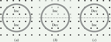
Hint: Induced current is proportional to the net change in magnetic field flux through the loop.
How Electric guitar works?
Look at the following figure
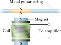
Presence of a permanent magnet makes the guitar wire a magnet.
When the magnetic guitar wire vibrates, it changes the magnetic flux in the coil.
This flux induces a current in the coil which exactly follow the vibrations of the guitar wire.
This current is fed to the amplifier and we can hear the sound of vibration of the guitar wire.
P = i2 R
P = i v
P = Fapp v
P = i B L v
P = Fapp i B/L
Induction and Energy Transfer.
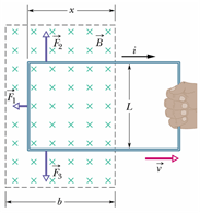
Consider a rectangular conducting wire loop placed in a uniform magnetic field (into the page).
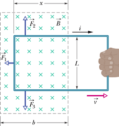
Since magnetic field is normal to the plane of the loop, the flux through the loop will be given as
![]()
Let us pull the loop with a constant velocity ![]() in positive x-direction.
in positive x-direction.
The change in magnetic flux due to this motion will induced emf E in the loop.

E is proportional to the length of the edge perpendicular to the direction of motion.
Relation between the power dissipated in loop and power delivered by applied force.
Let us draw an equivalent circuit of the loop to compute dissipated power ![]() in the loop.
in the loop.
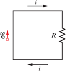
The current i through the loop can be computed from the induced emf E and the resistance R (any conductor always has some resistance) an.

Therefore power dissipated ![]() in the resistance R is given as
in the resistance R is given as

Power delivered by applied force
Magnetic force ![]() on any wire carrying current i is given as
on any wire carrying current i is given as
![]()
We can see that only three segments of the loop are in the magnetic field.
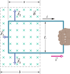
By right hand rule the direction of ![]() and
and ![]() are opposite to each other but the magnitude are same. These forces cancel each other.
are opposite to each other but the magnitude are same. These forces cancel each other.
Net force acting on loop will be sum of applied force ![]() and magnetic force
and magnetic force ![]() .
.
If the loop is moving with constant velocity, net force on it should be zero.
![]()
Therefore the applied force by us ![]() must be equal in magnitude to the magnetic force (which resists the motion of loop) acting on the loop.
must be equal in magnitude to the magnetic force (which resists the motion of loop) acting on the loop.
![]()
By substituting the value of induced current i in above equation we get

Power delivered by the applied force ![]() in moving the loop is given as
in moving the loop is given as

We can see that the power delivered ![]() in moving the loop is equal to power dissipated
in moving the loop is equal to power dissipated ![]() .
.
The work that you do in pulling the loop through the magnetic field appears as thermal energy in the loop.
Eddy Currents
Above statement is not only true for the loop but for any conductor.
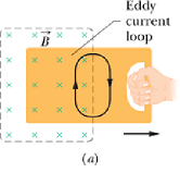
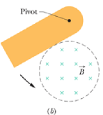
When ever a conductor is experiencing changing magnetic flux, the energy causing the change in flux appears as thermal energy in the conductor.
The induced currents generated in the conductor are called Eddy Currents.
 |
 |
andy currents
betty currents
curie currents
drew currents
eddy currents
Checkpoint 3
The figure shows four wire loops, with edge lengths of either L or 2L. All four loops will move through a region of uniform magnetic field ![]() (directed out of the page) at the same constant velocity. Rank the four loops according to the maximum magnitude of the emf induced as they move through the field, greatest first.
(directed out of the page) at the same constant velocity. Rank the four loops according to the maximum magnitude of the emf induced as they move through the field, greatest first.

Hint: Induced current is proportional to the length of the edge perpendicular to the direction of motion.
Electric field Induced by a Changing Magnetic Field
Presence of induced current in a conducting ring due to changing flux of magnetic field implies that an induced electric field ![]() is present.
is present.
Using above argument we can reformulate Faraday's las as follow:
A changing magnetic field produces an electric field.
This induced field is present even in the absence of the conducting ring.
Consider an imaginary circular path in a changing magnetic field.
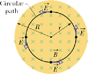
Let us consider that the charge completes one revolution around this path due to induced emf E.
Emf E in a circuit is defined as work done per unit charge in moving the charge from its initial to final position and in this case is given as

As per Faraday's law emf E in this situation is given as

By comparing these two equations we can find the relation between the induced electric field ![]() and change in magnetic flux
and change in magnetic flux ![]() .
.

In a uniform changing magnetic field, the line integral around a circular path of radius r is given as

Similarly change in magnetic flux ![]() is given as
is given as

Comparing these two equations give us the magnitude of induced electric field around the circular path of radius r as


an electric field.
an induced magnetic field.
a force field.
light.
global warming.
Inductance
Inductor:
Any conductor capable of producing magnetic field is called an inductor.
Flow of current through any conductor can produce magnetic field, therefore every conductor is an inductor.
Simple example of an inductor is a solenoid. The symbol of an inductor is also a solenoid (![]() ).
).
A capacitor produce electric field and an inductor produce magnetic field.
Inductance:
Consider a solenoid of length ℓ with N loops each of area A.
The number of loops per unit length n=N/ℓ.
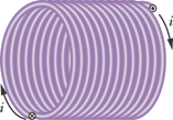
If i current is flowing through it, the magnetic field in the solenoid is given as
![]()
The magnetic flux through each loop is B A, so total magnetic flux ![]() through the solenoid is
through the solenoid is
![]()
By substituting the value of N we get
![]()
The term ![]() ℓA) is called inductance of the solenoid.
ℓA) is called inductance of the solenoid.
The symbol for inductance is L and , like capacitance, inductance also depends only on the geometrical parameters of a conductor.
![]()
The magnetic flux through the solenoid due to current i is given as
![]()
This relation is true for any shaped inductor.
SI Units for Inductance L is Henry (symbol H).
![]()
Self induced emf (self Induction):
Change in current in one loop can induced emf in a neighboring loop. Similarly when current changes in a loop or a solenoid, it induces emf in it self.
If current is changing in a solenoid or an inductor, the change in magnetic flux is given as

According the Faraday's law self induced emf E will be given as

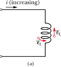 |
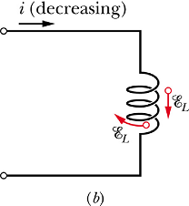 |
Alternative definition of 1 H
When a change of 1 A/s induce 1 V of emf in an inductor, its inductance is said to be 1 H.
Checkpoint 4
The figure shows an emf ![]() induced in a coil. Which of the following can describe the current through the coil: (a) constant and rightward, (b) constant and leftward, (c) increasing and rightward, (d) decreasing and right-ward, (e) increasing and leftward, (f) decreasing and leftward?
induced in a coil. Which of the following can describe the current through the coil: (a) constant and rightward, (b) constant and leftward, (c) increasing and rightward, (d) decreasing and right-ward, (e) increasing and leftward, (f) decreasing and leftward?
![]()
Hint: Induced emf always opposes the change in current. If current is increasing, it will decrease it if current is decreasing it will increase it.
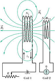
Mutual Inductance :
We know that when two coils are placed side by side, current ![]() in coil-1 will produce magnetic flux
in coil-1 will produce magnetic flux ![]() through the coil-2. Change in flux
through the coil-2. Change in flux ![]() will induce emf
will induce emf ![]() in coil-2.
in coil-2.

![]() is a constant and depends on the geometry of two coils and their relative position.
is a constant and depends on the geometry of two coils and their relative position.
 |
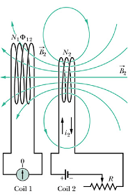 |
Similarly current ![]() in coil-2 will produce magnetic flux
in coil-2 will produce magnetic flux ![]() through the coil-1. Change in flux
through the coil-1. Change in flux ![]() will induce emf
will induce emf ![]() in coil-1.
in coil-1.

![]() is a again a constant and depends on the geometry of two coils and their relative position. It can be shown that for any two coils.
is a again a constant and depends on the geometry of two coils and their relative position. It can be shown that for any two coils.
![]()
M is called "Mutual Inductance" of two coils. SI Units for Mutual Inductance M is Henry (symbol H).
When a change of 1 A/s in one coil induce 1 V of emf in the other coil, their mutual inductance M is said to be 1 H.
Weber (Wb)
Henry (H)
ampere (A)
morgan (M)
volt (V)
RL Circuits
Rise of Current :
Consider a circuit as shown below.
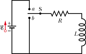
Suppose at time t=0 the switch is thrown in a position. The current will start increasing in the circuit and this increase will induce an emf ![]() across the inductor L. Now the equivalent circuit will be as shown below.
across the inductor L. Now the equivalent circuit will be as shown below.
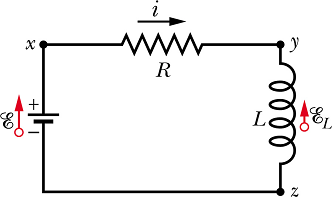
According to Kirchhoff rule
![]()
Where ![]() , above equation can be rewritten as
, above equation can be rewritten as

Solution of this equation gives us the current through the circuit at any time t.

This equation can be re written as

Here ![]() , the induced time constant, is given by
, the induced time constant, is given by

Plot of current as a function of time is given as
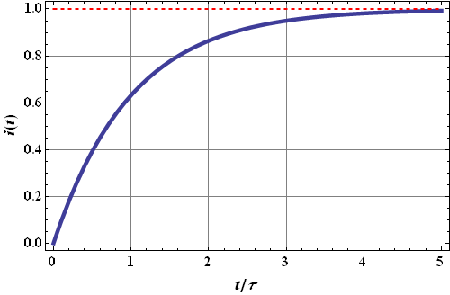
It can be seen that it takes a while (about 5τ time) for the current to reach its constant value.
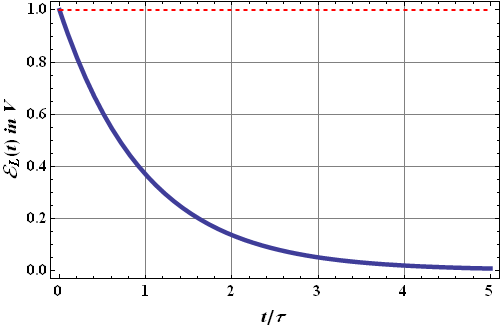
Once the current is constant, the induced emf ![]() . Change of
. Change of ![]() as a function of time is given as
as a function of time is given as
Decay of current :
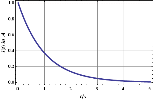
Once a steady current is flowing through the inductor and now if we throw the switch in b position. The current will not go to zero instantaneously.
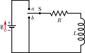
Suppose at time t=0 the switch is thrown in b position. The current will start decreasing in the circuit and this decrease will induce an emf ![]() across the inductor L. Now according to Kirchhoff's rule
across the inductor L. Now according to Kirchhoff's rule
![]()
Where ![]() , above equation can be rewritten as
, above equation can be rewritten as

Solution of this equation gives us the current through the circuit at any time t.

The time constant would increase to four times its original value.
The time constant would increase to twice its original value.
The time constant would remain the same.
The time constant would decrease to one-half its original value.
The time constant would decrease to one-fourth its original value.
Energy stored in an Inductor :
We have seen that energy is stored in electric field of a capacitor. Similarly energy is stored in the magnetic field of an inductor.
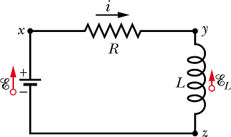
In the above circuit when current was building up the Kirchhoff's law gave following equation

If we multiply both sides by i we get

Left hand side term E i is the power delivered by the battery.
Right hand side term ![]() is the power dissipated in resistance R similarly
is the power dissipated in resistance R similarly  should be the (power) rate at which energy
 ![]() is being stored in inductor L.
is being stored in inductor L.

Current changes from zero to steady state value i, therefore total energy stored in the inductor is given as

Energy Stored in a Magnetic Field
Consider a solenoid of length ℓ , cross sectional area A and n number of loops per unit length. The energy stored in such an inductor will be

Volume of the solenoid is V=A ℓ, the energy density ![]() due to magnetic field in the solenoid is given as
due to magnetic field in the solenoid is given as

Magnetic field B produced in the solenoid is given as
![]()
By substituting the value of B in the expression for ![]() , we get
, we get

This expression is valid for any magnetic field B.
Compare it with the expression of electric energy density ![]() associated with electric field
associated with electric field

self-induction
coherence
interference
Lenz effect
mutual induction
in the inductance of the inductor
in the resistor
in the magnetic field
in the magnetic flux
in the current
