Images
Images are critical to a variety of fields and industries ranging from entertainment, to security, to medicine.
We learned about basic laws of reflection and refraction in geometric optics. In this chapter we will learn how to use these laws in the production of images.
Objectives
At the end of the chapter we should be able to answer following questions.
Classification of images
How image is produced by a plane mirror?
What are spherical mirrors?
How images are produced by spherical surfaces?
What are thin lenses?
How images are produced by thin lenses?
How lenses are used in some optical Instruments?
Classification of Images.
How we see things?
Our eye collects some light from the object and direct it (makes its image) onto the retina at the rear of the eye.
From retina, the signal goes to the brain and we make a perception about that object.
We always perceive that the light rays travel in a straight line and with this perception we estimate the direction and distance of the object.
There are two types of images.
Real Image and Virtual Image.
Real Image
Light rays are actually coming from the image.
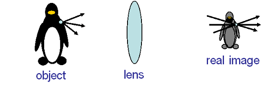
Image really exist in space or on a screen, whether you are looking or not.
Example: Image on a movie theater screen, image in a camera.
Virtual Image
No light ray is actually coming from the image. Only appear to be coming from image.
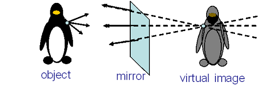
Virtual Image truly exist in the brain but never exist at the perceived location.
Example: our image in a mirror.
A Common Mirage
A common example of a virtual image is a pool of water that appears to lie on the road some distance ahead of you on a sunny day. That is called mirage.
Why we see mirage?
Light travels faster through warm air or warmer air has smaller index of refraction than colder air.
On a sunny day, air close to the surface of road is warmer than the air above it.
Light coming from top bends as shown in figure (b).
Actual path of light becomes as shown in figure (c).

The observer in car perceives as if light is coming from under the road although it is really coming from the sky.

The brain perceives as if it is the image of sky from a pool of water or a mirror is lying on the road.
How image is produced by a plane mirror?
Plane mirror is a flat reflecting surface.
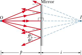
Any point source of light will send light rays in all direction.
Rays hitting the surface of a mirror will follow the law of reflection (angle of reflection is equal to angle of incidence)
 |
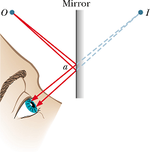 |
When these reflected rays enter the eye of an observer, brain perceives as if the rays are coming straight from some point at the back of the mirror.
How to find distance of the image from mirror surface?
Draw two rays from the object point O to the surface of the mirror. One normal to the surface and other making an angle θ.
Apply law of reflection and draw the reflected rays.
Extend these reflected rays (dotted) to the back of the mirror.
The point of intersection will be the position of virtual image.
Virtual image distance from the mirror surface is always taken as negative.
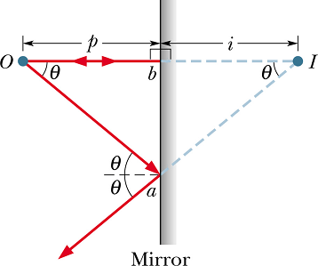
△ aOb and △ aIb are identical triangles, therefore
![]()
In virtual image convention we can write
![]()
In a plane mirror distance of virtual image is equal to the distance of object from the mirror surface.
Extended Object:
Although we have described the image properties using a point source. The properties will be same for an extended object.
Each point source of light in the extended object is mapped to a point in the image.
Mirror Maze:
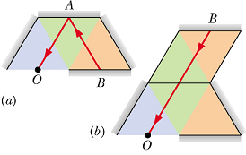
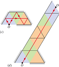
Your eye traces incoming rays straight back, and cannot know that the rays may have actually been reflected many times.
 |
 |
Checkpoint 1
In the figure you are in a system of two vertical parallel mirrors A and B separated by distance d. A grinning gargoyle is perched at point O, a distance 0.2d from mirror A. Each mirror produces a first (least deep) image of the gargoyle. Then each mirror produces a second image with the object being the first image in the opposite mirror. Then each mirror produces a third image with the object being the second image in the opposite mirror, and so on—you might see hundreds of grinning gargoyle images. How deep behind mirror A are the first, second, and third images in mirror A?
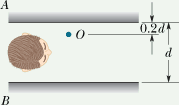
Hint : In a plane mirror, the distance of image from mirror surface is equal to the distance of object from the mirror surface.
What are spherical Mirrors?
Spherical mirrors are the mirrors in the shape of a small section of a sphere.
The center of the sphere (from which these mirrors are made) is called center of curvature C.
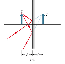
Plane Mirror :
Plane mirror is a kind of spherical mirror with center of curvature at infinity, or is a section of a sphere with infinite radius.
Concave Mirror :
When the reflecting surface is "caved in" we call it a concave mirror.
Center of curvature is closer than plane mirror, and is in front of the reflecting surface.
Field of view is smaller than plane mirror.
Image of the object is formed farther behind in concave mirror than in plane mirror.
Size of image in concave mirror is more than the size of the object.
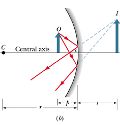
Shaving mirror is an example of concave mirror.
Convex Mirror :
When the reflecting surface is "flexed out", we call it a convex mirror.
Center of curvature is closer but is in the back of the reflecting surface.
Field of view is larger than plane mirror.
Image of the object is formed closer behind a convex mirror than plane mirror.
Size of image in convex mirror is smaller than the size of the object.
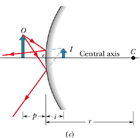
Rear viewing mirror in a car is an example of convex mirror.
Focal Points of Spherical Mirrors:
A line drawn through the center of curvature C and the central point c on the spherical mirror is called central axis.
Concave Mirror :
All the rays parallel to the central axis of a concave mirror are reflected through a common point as shown in the figure below. This point is called the focal point F, of the mirror as shown in the figure.
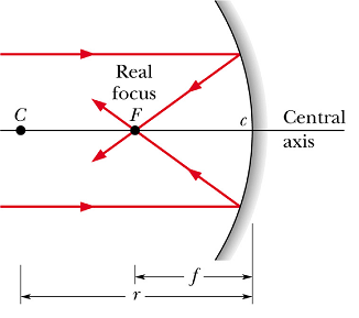
For a concave mirror the focal length f is taken as positive.
Convex Mirror :
All the rays parallel to the central axis of a convex mirror are reflected in such a way that all theas rays appear to be originating from a common point as shown in the figure below. This point is called the focal point F, of the mirror as shown in the figure.
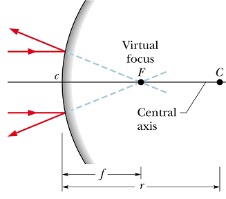
For a convex mirror the focal length f is taken as negative.
For both the mirrors, the focal length is related to the radius of curvature r of the mirror.
![]()
How to compute parameters of images produced by spherical Mirrors?
Image Position :
Once we know the focal point of spherical Mirror, the relation between the object distance p and image distance i is given as

For virtual image the image distance i is taken as negative.

In spherical mirrors, real images form on the side of the object, and virtual images form on the opposite side.
Concave Mirror :
Convex Mirror :
Image Magnification :
The ratio of height of image to that of object is called lateral magnification m.
If h' is the height of image and h is the height of object, then

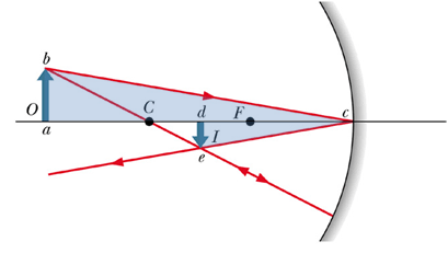
Let us look at the above figure. The shaded triangles, △abc, and △dec are similar triangles. Therefore ratio of their corresponding side should be same.

de=h' the height of image and ab=h the height of object. Similarly ac=p the object distance and dc=i the image distance, we can write the above equation as

Minus sign indicate that image is inverted (distance de is negative). Above expression is true for any spherical mirror (concave or convex).
Checkpoint 2
A Central American vampire bat, dozing on the central axis of a spherical mirror, is magnified by m = −4. Is its image (a) real or virtual, (b) inverted or of the same orientation as the bat, and (c) on the same side of the mirror as the bat or on the opposite side?
Hint : Negative magnification means inverted image.
Spherical Refracting Surfaces
Like reflection, refraction can also form images.
We will consider only spherical refracting surfaces.
In refracting surfaces, real images form on the opposite side of the object (side to which light is going).
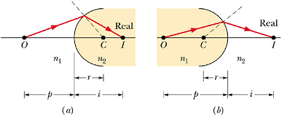
Virtual images form on the same side as the object.

Rules for Refractive surfaces
When object faces a convex refracting surface radius of curvature r is positive. When it faces a concave surface, r is negative.
CAUTION: This is reverse of mirror sign convention!
Line joining the object point and central point of the spherical surface is called central axis.
We will only consider rays making small angles with central axis, such that θ≈sinθ.
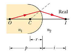
When rays form small angles with central axis, the distance of object p and image distance i are related to the radius of curvature r by following formula.

How images are produced by thin lenses?
What is a lens?
A lens is a transparent object with two refracting surfaces whose central axes coincide.
A lens can produce an image of an object only because the lens can bend light rays, but it can bend light rays only if its index of refraction differs from that of the surrounding medium.
Since a lens is made up of two spherical surfaces, therefore it has two focal lengths ![]() and
and ![]() .
.
Point ![]() and
and ![]() are called 2f points (they are not center of curvature).
are called 2f points (they are not center of curvature).
A lens that converges the parallel light rays incident on the lens surface, is (reasonably) called a converging lens.
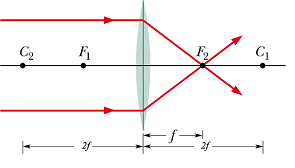 |
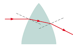 |
A lens that causes light rays to diverge, is called a diverging lens.
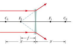 |
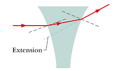 |
Thin Lens
Thin lens is the one, in which the thickest part is very thin relative to the object distance p, the image distance i, and the radii of curvature ![]() and
and ![]() of the two lens surfaces.
of the two lens surfaces.
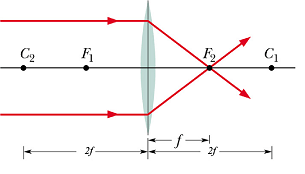 |
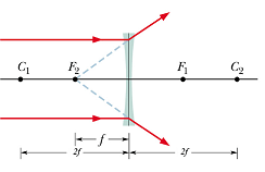 |
For a thin lens, the two focal points ![]() and
and ![]() are equidistant (f) from the lens.
are equidistant (f) from the lens.
Focal length f of a thin lens in air is given as

For a ray facing convex surface, r is taken as positive.
For a ray facing concave surface, r is taken as negative.
In case of a thin lens, relation between the object distance p and the image distance i is given as

Locating images by drawing rays
Converging Lens
A ray initially parallel to central axis will pass through focal point ![]() .
.
A ray that initially is directed toward the center of the lens will emerge from the lens with no change in its direction (the two sides of the lens at the center are almost parallel).
A ray that initially passes through focal point ![]() , will emerge parallel to central axis.
, will emerge parallel to central axis.
Because the focal points of a converging lens are real, we take the associated focal lengths f to be positive.
We can see that with a converging lens the image is virtual when object is between the focal point and lens surface.
Diverging Lens
A ray initially parallel to central axis will appear to be coming through focal point ![]() .
.
A ray that initially is directed toward the center of the lens will emerge from the lens with no change in its direction (the two sides of the lens at the center are almost parallel).
A ray that initially appears to be passing through focal point ![]() , will emerge parallel to central axis.
, will emerge parallel to central axis.
Because the focal points of a diverging lens are virtual, we take the associated focal lengths f to be negative.
Problem 1:
A lens is made of glass having an index of refraction of 1.5. One side of the lens is flat, and the other is convex with a radius of curvature of 20 cm. (a) Find the focal length of the lens. (b) If an object is placed 40 cm in front of the lens, where will the image be located?
How we perceive size of an Objects?
When an object is located anywhere from infinity to a certain point called the near point ![]() , the normal human eye can focus a sharp image of this object on the retina (at the rear of the eye).
, the normal human eye can focus a sharp image of this object on the retina (at the rear of the eye).

The value of ![]() changes with age and can be different for different persons.
changes with age and can be different for different persons.
Typical value of near point ![]() is taken as 25 cm.
is taken as 25 cm.
The size of the image of the object produced on the retina depends on the angle θ that the object occupies in the field of view of the eye.
If we move the object closer to eye, θ increases therefore the perceived size increases and we can see the object more clearly.
Simple Magnifying Glass
When we move the object closer than the near point ![]() , the perceived retina image becomes fuzzy.
, the perceived retina image becomes fuzzy.

What will happen to this fuzzy image, if we insert a converging lens between the object and the eye, such that the focal length f>p?
A distant virtual image will be formed as shown.
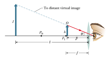
If h' is the image size, angle θ' subtended by the image is

Here we are using the fact that h'/h=i/p, where h is the height of the object.
In the absence of lens the maximum angle θ, the object can subtend without getting fuzzy is when it is placed at ![]() . Therefor
. Therefor

The angular magnification ![]() of the magnifying lens is now given as
of the magnifying lens is now given as

Or

What is the Maximum Magnification of a magnifying lens?
For a magnifying glass (for virtual image) p should always satisfy the condition p≤ f.

As per above equation, for negative value of i (virtual image), if p is reduced, i will be reduced as f is a constant.
Minimum value of i at which we can clearly see the image is ![]() ( image should be virtual).
( image should be virtual).
By substituting the value of ![]() , we get the smallest value of p, where a clear image can be seen.
, we get the smallest value of p, where a clear image can be seen.

Maximum angular magnification ![]() of a magnifying glass is
of a magnifying glass is

Above equation can be rewritten as

Shorter the focal length, larger the angular magnification ![]() of the magnifying lens.
of the magnifying lens.
Problem 2:
Someone with a near point ![]() of 25 cm views a thimble through a simple magnifying lens of focal length 10 cm by placing the lens near his eye.What is the angular magnification of the thimble if it is positioned so that its image appears at (a)
of 25 cm views a thimble through a simple magnifying lens of focal length 10 cm by placing the lens near his eye.What is the angular magnification of the thimble if it is positioned so that its image appears at (a) ![]() and (b) infinity?
and (b) infinity?
Solution :
Magnification of a magnifying glass is given as

If image appear at ![]() , the image distance
, the image distance ![]() The focal length f=10 cm.
The focal length f=10 cm.
The position of object (thimble) can be calculated by using the formula

We can rewrite it as

![]()
![]()
Angular magnification is


![]()
If image appear at infinity, the image distance i=-∞ cm.The focal length f=10 cm.
The position of object (thimble) can be calculated by using the formula

If i=∞,


![]()
Two Lens System :
Before we move to multi lens instruments, let us consider a two lens system.

Let ![]() be the distance of object O from Lens 1. Use the following equation or ray drawing method to determine the distance
be the distance of object O from Lens 1. Use the following equation or ray drawing method to determine the distance ![]() to the image of Lens 1.
to the image of Lens 1.

Ignore the presence of lens 1, and use ![]() as the object
as the object ![]() .
.

If ![]() is located beyond Lens 2, treat it as a virtual object and use a negative object distance
is located beyond Lens 2, treat it as a virtual object and use a negative object distance ![]() . Determine
. Determine ![]() using the image equation.
using the image equation.
A similar step by step solution can be used for any number of lenses.
Overall lateral magnification M of two lens system is product of two lateral magnifications ![]() and
and ![]() .
.
![]()
Compound Microscope:
Compound microscope is a two lens system with separation of lenses “s”, much larger than the sum of two focal lengths ( ![]() and
and ![]() ).
).
![]()
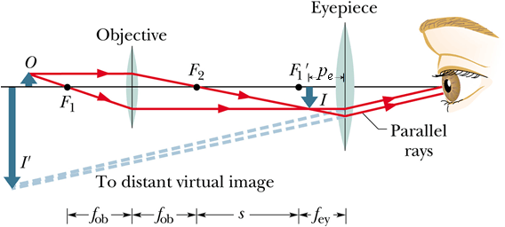
If h is the height of the object O, the height h' of image I will be given as.
![]()
Where m is the lateral magnification of the objective lens.
Image I due to objective lens is positioned at ![]() such that
such that ![]() .
.
Now the angle θ subtended by image I can be given as

In the absence of microscope the maximum angle θ', the object can subtend without getting fuzzy is when it is placed at near point ![]() . Therefor
. Therefor

Overall perceived size magnification M of the microscope will be

Or

We can see that overall magnification M of a microscope is the product of lateral magnification m of the objective lens and angular magnification ![]() of the eyepiece lens.
of the eyepiece lens.
Maximum Magnification of a Microscope
Lateral magnification m of objective is

For a real image object distance ![]() . Therefore minimum value of
. Therefore minimum value of ![]() .
.
Maximum image distance ![]() .
.
Generally in a microscope ![]() , therefore
, therefore ![]() .
.
Maximum lateral magnification of objective can be written as

Maximum angular magnification ![]() of eye piece is
of eye piece is

Maximum magnification ![]() of a compound microscope is
of a compound microscope is

We can see that in a compound microscope, smaller the two focal lengths ![]() ,
, ![]() ), larger the magnification M.
), larger the magnification M.
Refracting Telescope:
Refracting Telescope is a two lens system with the separation s of lenses, equal to the sum of the focal lengths ( ![]() and
and ![]() ) of two lenses.
) of two lenses.
![]()

In this case the object can be assumed to be at infinity.
The image due to objective will be at its focal point ![]() .
.
We know that any ray passing through the center of the lens, do not bend. We can use this ray to calculate angle θ' subtended by the object at the observation point before entering telescope.
![]()
θ' gives the maximum size of a distant object we can see in the absence of telescope.
Eyepiece lens makes a virtual image I' of the image I produced by objective.
If h is the height of image I and ![]() is its distance from eyepiece, angle θ subtended by the magnified virtual image is
is its distance from eyepiece, angle θ subtended by the magnified virtual image is

Negative sign corresponds to inverted image. Similarly

No negative sign as the magnitude of ![]() is equal to θ'.
is equal to θ'.
Overall perceived magnification M of the object will be

Or

Maximum Magnification of a Refracting Telescope
Magnification of telescope will be maximum when ![]() is minimum.
is minimum.

For a magnifying glass (eye piece) minimum ![]() is given as
is given as

Maximum magnification ![]() of a refracting telescope
of a refracting telescope

If ![]() (this is generally the case), we can write
(this is generally the case), we can write ![]() .
.
![]() of a refracting telescope will be given as
of a refracting telescope will be given as

We can see that in a Refracting Telescope, for larger magnification, focal length of objective ![]() should be larger and focal length of eyepiece
should be larger and focal length of eyepiece ![]() should be smaller.
should be smaller.
