Equilibrium and Elasticity
This chapter has two section, in first section we will learn about equilibrium. After finishing this section we should know following topics:
Definition of equilibrium.
Conditions needed for an object to be in equilibrium.
Recipe for solving static equilibrium problems.
Center of gravity and its relation with center of mass.
Indeterminate structures.
In this section we will examine how a “rigid” body can be deformed by an external force. After finishing this section we should know following topics:
Stress and Strain
Young’s modulus (in connection with tension and compression)
Shear modulus (in connection with shearing)
Bulk modulus (in connection to hydraulic stress)
When is an object said to be in equilibrium?
An object is in equilibrium when
The linear momentum ![]() of its center of mass is constant.
of its center of mass is constant.
Its angular momentum ![]() about its center of mass, or about any other point, is also constant.
about its center of mass, or about any other point, is also constant.
![]()
In this chapter we will deal with situations where the value of these constants are zero.
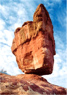 |
| Static Equilibrium |
When linear momentum ![]() , the object is said to be in static equilibrium.
, the object is said to be in static equilibrium.
Types of Static Equilibrium
There are two kinds of static equilibrium
Stable: When an external force disturbs the static equilibrium, but object returns back to its static equilibrium
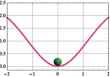
Unstable: When an object, after getting disturbed by an external force, could not return back to its static equilibrium.
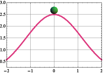
Requirements of Equilibrium
According to Newton’s second law for linear momentum.

Similarly Newton’s second law for angular momentum.

When ![]() and
and ![]() are constants,
are constants, ![]() and
and ![]() .
.
The vector sum of all the external forces that act on the body must be zero. ![]()
The vector sum of all external torques that act on the body, measured about any possible point, must also be zero. ![]()
For static equilibrium
The linear momentum ![]() .
.
The person on the train would say that the block is in static equilibrium, but the external observer would say that the block is in equilibrium, but not static equilibrium.
The person on the train would say that the block is in equilibrium, but not static equilibrium; and the external observer would say that the block is in static equilibrium.
Both the person on the train and the external observer would agree that the block is in equilibrium, but not static equilibrium.
The person on the train would say that the block is in equilibrium, but the external observer would say that the block is not in equilibrium.
Both the person on the train and the external observer would agree that the block is not in equilibrium.
In three dimensions, conditions for equilibrium are written as:
| Balance of forces | Balance of torques |
For simplicity we will only consider situations, in which forces always act in x, y plane.
That means torque will always be directed along z-axis.
The above six conditions for equilibrium, will reduce to simple three conditions.
![]()
![]()
![]()
Here ![]() is the net torque that the external forces produce either about z-axis or any axis parallel to it.
is the net torque that the external forces produce either about z-axis or any axis parallel to it.
Recipe for solving static equilibrium problems:
Draw a force diagram. (Label the axes).
Choose a convenient origin O.
A good choice is to have one of the unknown forces acting at the origin O.
Compute net torque due to all the forces about O.
Value of net torque ![]() usually depends on the choice of origin, but when net force acting on an object
usually depends on the choice of origin, but when net force acting on an object ![]() , the value of net torque
, the value of net torque ![]() becomes independent of the choice of origin.
becomes independent of the choice of origin.
Torque τ due to a force F is given as ![]() where
where ![]() is moment arm.
is moment arm.
For computing moment arm, draw a line through the line of force and draw a perpendicular to this line from point O.
![]() is the perpendicular distance between O and the line of action of F.
is the perpendicular distance between O and the line of action of F.
Find out the sign of the torque due to each force.
Sign is negative if the force induces clockwise (CW) rotation.
Sign is positive if the force induces anticlockwise (CCW) rotation.
Equilibrium conditions
![]()
![]()
![]()
Make sure that: numbers of unknowns = number of equations
Checkpoint-1: (Equilibrium)
The figure gives six overhead views of a uniform rod on which two or more forces act perpendicularly to the rod. If the magnitudes of the forces are adjusted properly (but kept nonzero), in which situations can the rod be in static equilibrium?

Hints :
Net force should be zero and net torque around any axis should be zero.
Problem 1: (Equilibrium)
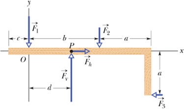
Forces ![]() ,
, ![]() , and
, and ![]() act on the structure of following figure, shown in an overhead view. We wish to put the structure in equilibrium by applying a fourth force, at a point such as P. The fourth force has vector components
act on the structure of following figure, shown in an overhead view. We wish to put the structure in equilibrium by applying a fourth force, at a point such as P. The fourth force has vector components ![]() and
and ![]() . We are given that a=2.0m , b=3.0 m, c=1.0m,
. We are given that a=2.0m , b=3.0 m, c=1.0m, ![]() ,
, ![]() , and
, and ![]() .
.
Find (a) ![]() , (b)
, (b) ![]() , and (c) d.
, and (c) d.
Solution :
Net vertical forces will give us
![]()
Therefore
![]()
Net horizontal force will give us
![]()
![]()
Torque about O will give us
![]()
![]()

Problem 2: (Equilibrium)
Following figure shows a 70 kg climber hanging by only the crimp hold of one hand on the edge of a shallow horizontal ledge in a rock wall. (The fingers are pressed down to gain purchase.) Her feet touch the rock wall at distance H=2.0m directly below her crimped fingers but do not provide any support. Her center of mass is distance a=0.20m from the wall. Assume that the force from the ledge supporting her fingers is equally shared by the four fingers.
What are the values of the (a) horizontal component ![]() and (b) vertical component
and (b) vertical component ![]() of the force on each fingertip?
of the force on each fingertip?
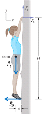
Solution :
First calculate net force along x-axis and net force along y-axis
![]()
![]()

Three forces are unknown, ![]() ,
, ![]() , and
, and ![]() . Let us choose origin at the point of action of normal force
. Let us choose origin at the point of action of normal force ![]() . Now we can calculate torque around origin.
. Now we can calculate torque around origin.


Problem 3: (Equilibrium)
In the figure, a uniform beam of weight 500 N and length 3.0 m is suspended horizontally. On the left it is hinged to a wall; on the right it is supported by a cable bolted to the wall at distance D above the beam. The least tension that will snap the cable is 1200 N.
What value of D corresponds to that tension?
To prevent the cable from snapping, should D be increased or decreased from that value?.
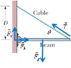
Solution :
Net vertical forces will give us
![]()
![]()
Torque about hinge will give us


It means  , therefore larger the θ (larger D), better it will be.
Center of Gravity
Consider a rigid body made up of four atoms or molecules as shown.
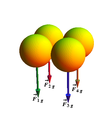
Total gravitational force ![]() acting on the body is vector sum of gravitational force acting on individual atoms/molecules.
acting on the body is vector sum of gravitational force acting on individual atoms/molecules.
![]()
If we replace all the forces by the net force ![]() acting on a single point, such that the net torque (about any point) acting on the body would not change, the point is called the center of gravity (cog) of the body.
acting on a single point, such that the net torque (about any point) acting on the body would not change, the point is called the center of gravity (cog) of the body.
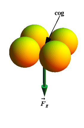
The gravitational force ![]() on a body effectively acts at a single point, called the center of gravity (cog) of the body.
on a body effectively acts at a single point, called the center of gravity (cog) of the body.
If value of g (acceleration due to gravity) is the same for all elements of a body, then the body’s center of gravity (cog) is coincident with the body’s center of mass (com)
In each case, the forces may act at the center of gravity or at the a corner.
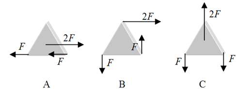
A only.
B only.
C only.
A and C.
A and B.
Indeterminate Structures
To solve equilibrium problems, we have only three independent equations at our disposal.
Thus, if a problem has more than three unknowns, we cannot solve it.
Consider an asymmetrically loaded car. What are the forces on the four tires?
Again, we cannot find forces on four tires as we only have three independent equations.
Problems in which there are more unknowns than equations, are called indeterminate.
Yet solutions to indeterminate problems exist in the real world.
If you rest the tires of the car on four platform scales, each scale will register a definite reading, the sum of the readings being the weight of the car.
What is eluding us in our efforts to find the individual forces by solving equations?
Checkpoint-2: ( Indeterminate)
A horizontal uniform bar of weight 10 N is to hang from a ceiling by two wires that exert upward forces ![]() and
and ![]() on the bar. The figure shows four arrangements for the wires.
on the bar. The figure shows four arrangements for the wires.
Which arrangements, if any, are indeterminate (so that we cannot solve for numerical values of ![]() and
and ![]() )?
)?
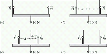
Hint: Find out which arrangement has more than three unknowns.
A ball-spring model for a solid object
Earlier we have learned that simple spring ball model shown in the figure has all the features we need to understand a rigid body.
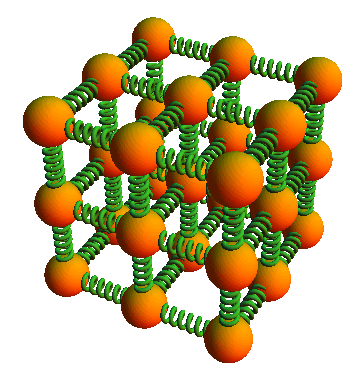
This model indicates that, all “rigid” bodies are to some extent elastic, which means, we can change their dimensions slightly by pulling, pushing, twisting, or compressing them.
Stress and Strain
When a force acts on a solid object, it might change its dimensions.
Deforming force per unit area is known as stress.
The resulting deformation is called strain and is proportional to the applied stress.
There are three ways in which a solid might change its dimensions when force acts on it. Accordingly we define three types of stress.
Tensile and compressive Stress.
Shearing Stress.
Hydraulic Stress.
If the stress is increased beyond the yield strength of the specimen, the specimen becomes permanently deformed.
If the stress continues to increase, the specimen eventually ruptures, at a stress called the ultimate strength.
Tensile and compressive Stress:
Consider a cylinder, stretched by a deforming force ![]() applied along its length.
applied along its length.
With applied force along the length, we can stretch or compress an object and change its length.
In case of stretching, it is called tensile stress.
In case of compression, it is called compressive stress.
In stretching and compression, deformation is change in length.
Change in length per unit length (ΔL/L) is proportional to applied stress (force per unit area).

Here F is the magnitude of applied force and A is the area surface on which force is acting.
The constant E is called Young’s modulus.
Shearing Stress:
Consider a cylinder deformed by a force ![]() perpendicular to its long axis, much as we might deform a pack of cards or a book.
perpendicular to its long axis, much as we might deform a pack of cards or a book.
In this case force vector ![]() lies in the plane of the area rather than perpendicular to it.
lies in the plane of the area rather than perpendicular to it.
When force vector lies in the plane of area, the stress computed from such force is called shearing stress.
Strain in this case is defined as Δx/L, and is proportional to the applied stress.

The constant G is called shear modulus.
Hydraulic Stress:
Consider a solid object placed in a fluid under high pressure. It is compressed uniformly on all sides.
In this case stress equal to the applied pressure P, which is again defined as the force applied per unit area.
It is called hydraulic stress and the object is said to be under hydraulic compression.
Deformation or strain is defined as fractional change in volume ΔV/V and is proportional to applied stress.

Here V is the original volume and ΔV is the change in volume.
The constant B is called bulk modulus.
The one with the circular cross section will stretch more.
The one with the square cross section will stretch more.
Both will stretch by the same amount.
One cannot say which will stretch more without knowing the numerical values of a and m.
Problem 4: (Elasticity)
A 4.0m long steel beam with a cross-sectional area of ![]() and a Young's modulus of
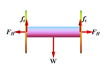
and a Young's modulus of ![]() is wedged horizontally between two vertical walls. In order to wedge the beam, it is compressed by 0.020 mm. If the coefficient of static friction between the beam and the walls is 0.70.
is wedged horizontally between two vertical walls. In order to wedge the beam, it is compressed by 0.020 mm. If the coefficient of static friction between the beam and the walls is 0.70.
What is the maximum mass (including its own) it can bear without slipping?
Solution :
Force of friction ![]() should balance the maximum weight W.
should balance the maximum weight W.
![]()
Maximum force of static friction is related to the normal force exerted by the walls, which is equal to horizontal force ![]() exerted by the steel beam on the walls.
exerted by the steel beam on the walls.
![]()
![]()
Force exerted by the beam is generated due to compression of its length L by ΔL from both ends. A is the cross sectional area and E is Young's modulus.s.


Cut the wire in half and use one half to hang the ball from the ceiling.
Replace the wire with one of identical dimensions, but composed of tungsten.
Replace the ball with one with one half the mass of the original ball.
Connect the pendulum to a fixture that allows the pendulum to swing closer to the ground.
Replace the wire with one made of the same material and of the same length, but with a diameter 2d.
