Circuits
Objectives
In this chapter we will introduce the following concepts
Electromotive force (emf)
Ideal and real emf devices
Kirchhoff’s loop rule
Kirchhoff’s junction rule
Multiloop circuits
Resistors in series
Resistors in parallel
RC circuits, charging and discharging of a capacitor
Electromotive force (emf)
A "charge pump" is needed to produce a steady flow of charges through a resistor.
In other words a device is needed to maintain a potential difference between a pair of terminals.
Such a device is called an emf device.
It is also called a seat of emf.
emf device supplies the energy for the motion of charges.
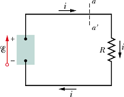
emf of the device is represented by an arrow with a small circle on the tail.
The arrow points from the negative terminal toward the positive terminal.
 |
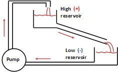 |
In mechanical analog a water pump transfers water from low to high reservoir.
The pipe through which, the water flows, is the analog of the resistor.
The term emf comes from the outdated phrase electromotive force, which was adopted before scientists clearly understood the function of an emf device.
Examples : Battery, electric generator, solar cells, fuel cells (power the space shuttles), thermopiles (provide onboard electrical power for some spacecraft).
living systems, ranging from electric eels and human beings to plants, have physiological emf devices.
Work, Energy, and emf
Consider a simple electric circuit.
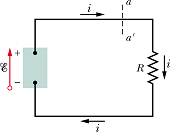
Suppose a charge dq passes through any cross section of this circuit, such as aa'.
It means charge dq leaves the high - potential end and enter the low - potential end of emf device after passing through resistor R.
To maintain a continuous flow, inside the device, the charge dq must be moved (pumped) from low-potential to high-potential.
For pumping of charge, the device must do work dW on the charge dq.
The emf of the device is defined in terms of work done by the device per unit charge:

emf of a device is the work per unit charge that the device does in moving charge from its low - potential terminal to its high - potential terminal.
SI unit for emf is the joule per coulomb; This is defined as the volt.
Ideal and Real emf device.
If V is potential difference across terminals a and b, the emf device is said to be ideal emf device when
![]()
In ideal emf device V does not depend upon the current i, that flows through the device.
In real devices the potential difference V across terminals a and b is given by equation
![]()
Here r is known as the internal resistance of the emf device
E is positive as it is potential difference between low to high, while r×i is potential difference between high to low.
Internal resistance of an ideal emf device is zero.
Point to Remember :
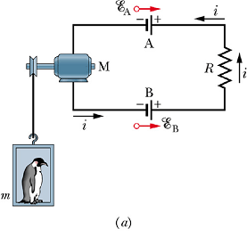
When the direction of red arrow is same as direction of current, emf device does the work.
When red arrow is anti parallel to current direction work is done on the emf device.
 |
 |
In the circuit shown in figure (a), red arrow of emf device B is parallel to the current direction while red arrow for device A is anti parallel
The work is only done by emf device B.
Work is done on motor, emf device A (for charging) and resistor R.
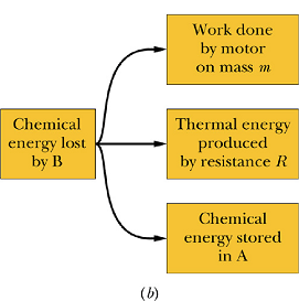
Energy flow chart is shown in figure (b).
Checkpoint 1
The figure shows the current i in a single-loop circuit with a battery B and a resistance R (and wires of negligible resistance),
(a) Should the emf arrow at B be drawn pointing leftward or rightward?
At points a, b, and c, rank (b) the magnitude of the current, (c) the electric potential, and (d) the electric potential energy of the charge carriers, greatest first.
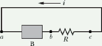
Current in a Single-Loop Circuit
Energy Method
Assume that current i flows through the circuit due to emf E supplied by the emf device.
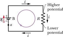
If dq is the charge flowing through the circuit in time dt

The work done by the emf device in moving charge dq is
![]()
The power ![]() delivered by emf device is
delivered by emf device is

Power dissipated in the resistor R is given as
![]()
Now the power delivered by emf device should be equal to the power dissipated in the resistor R (It is assumed that the resistance of all the connecting wires is zero)
![]()
Above equation gives relation between E and i as

Potential Method
LOOP RULE: The algebraic sum of the changes in potential encountered in a complete traversal of any loop of a circuit must be zero.
This is referred to as Kirchhoff' s loop rule or Kirchhoff' s voltage law.
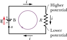
If we start from point a and come back to point a the total potential difference should be zero.
Let us move along the current, potential difference across emf device from negative terminal to positive terminal is +E, potential difference across resistor R is v=-i R, it is negative as we are moving from higher potential to lower potential.
Net potential difference after coming back to a is
![]()
or

Points to remember :
For measuring potential difference.
Current always flow from higher to lower potential.
Inside an emf device, charges flow from lower to higher potential.
RESISTANCE RULE: For a move through a resistance in the direction of the current, the change in potential is −i R; in the opposite direction it is +i R.
emf RULE: For a move through an ideal emf device in the direction of the emf arrow, the change in potential is +E; in the opposite direction it is -E.
Other Single loop Circuits
Internal resistance:
Consider a real emf source with internal resistance r connected to a resistance R.

If we apply the loop rule clockwise beginning at point a, the changes in potential give us
![]()

Figure b shows change in potential across different elements of the circuit.
Resistances in Series
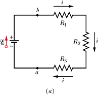
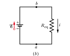
When a potential difference V is applied across resistances connected in series, the resistances have identical currents i.
The sum of the potential differences across the resistances is equal to the applied potential difference V.
 |
 |
In the above circuit sum of different potentials can be given as
![]()
![]()
When resistors are connected in series, equivalent resistor ![]() is given as
is given as
![]()
The extension to n resistances in series is straightforward and is

Checkpoint 2
In the figure, if R1 > R2 > R3, rank the three resistances according to (a) the current through them and (b) the potential difference across them, greatest first.
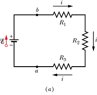
Hint: Current is same through all the elements.
Checkpoint - 3 (Current in single loop)
Two bulbs are connected in series with a 12 V emf device.
(a) What will be the value of current through loop when both the bulbs have same resistance of 10 Ω?
(b) will the brightness of both equal or different? (Hint: brightness of a bulb is proportional to the power consumed)
(c) If we increase the resistance ![]() , how the current will change?
, how the current will change?
(d) If we increase the resistance ![]() , how the brightness of the two bulbs will change?
, how the brightness of the two bulbs will change?
(e) What will happen to brightness of bulbs when we increase ![]() ?
?
Potential Difference between two points.
Consider the following circuit. How to calculate potential difference ![]() ?
?
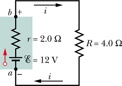
Step-1: Assume potential at point a is ![]() and potential at point b is
and potential at point b is ![]() .
.
Step-2 : Start from point a and go along the path of current, add potential difference across any device in the path from a to b.
Step-3: This added up potential should be equal to potential ![]() at point b.
at point b.
![]()
![]()
Now we know E and internal resistance r, but we do not know current i.
Step-4: Total resistance across the emf device is r+R, calculate current i as below

Step-5: Substitute the value of current i in equation giving us ![]() .
.

We can substitute the values of E, r and R of a given circuit and found the value of ![]() .
.

![]()
Similarly current i through the circuit is

![]()
Potential Difference Across a Real Battery
The points are located on the terminal of a real battery, therefore the terminal to the terminal potential difference V across the battery is
![]()
Grounding a Circuit
Symbol for ground is ![]() . Grounding the circuit usually means connecting the circuit to a conducting path to Earth.
. Grounding the circuit usually means connecting the circuit to a conducting path to Earth.
When terminal a is Grounded, potential at a is defined to be ![]() , so in above example
, so in above example ![]() .
.
When terminal b is Grounded, potential at b is defined to be ![]() , so in above example
, so in above example ![]() .
.
Power of Emf Device
The power delivered by emf device to an external device connected to its terminals (Say a fan) is given as
![]()
V is the potential across the terminals of the device. If we substitute the value of V obtained earlier
![]()
The term ![]() corresponds to the internally dissipated power. The power of emf device will be i E.
corresponds to the internally dissipated power. The power of emf device will be i E.
![]()
![]()
Emf device transfers energy both to the charge carriers and to the internal thermal energy.
When you recharge a battery, you have to supply energy for the battery and for the thermal energy loss in internal resistance.
Checkpoint - 4 (Potential Difference between two points)
A 20 Ω Fan is connected with a 12 V emf device.
(a) When the switch is open what is the potential difference across terminals a and b?
(b) When the switch is closed what will be potential difference across a and b?
(c) If the internal resistor r increases, will the potential difference across a and b increase, decrease or remain same?
(d) If the internal resistor r increases, will the current in the loop increase, decrease or remain same?
(e) How the speed of the fan will change with current i?
Problem - 1 (Potential Difference between two points)
(a) In the following figure, what value must R have if the current in the circuit is to be 1.0 mA? Take ![]() ,
, ![]() and
and ![]() . (b) What is the rate at which thermal energy appears in R?
. (b) What is the rate at which thermal energy appears in R?
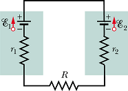
Since ![]() , we can say that the direction of current i is dictated by
, we can say that the direction of current i is dictated by ![]() and it is anti-clockwise.
and it is anti-clockwise.
Total resistance ![]() in the circuit is given as
in the circuit is given as
![]()
Let us find the applied potential difference ![]() to all the resistors. It is the potential difference across negative terminals of the emf devices. We start from negative terminal of device
to all the resistors. It is the potential difference across negative terminals of the emf devices. We start from negative terminal of device ![]() and go along the direction of current (we have assumed it to be anti-clockwise). Red arrow of
and go along the direction of current (we have assumed it to be anti-clockwise). Red arrow of ![]() is pointing opposite to the current, therefore it is negative, red arrow of
is pointing opposite to the current, therefore it is negative, red arrow of ![]() is pointing parallel to the current so it is positive.
is pointing parallel to the current so it is positive.
![]()
Now the current through the resistor will be given as

Solving the above equation we get the value of R


![]()
Power disputed in resistor R will be given as
![]()

![]()
Multiloop Circuits
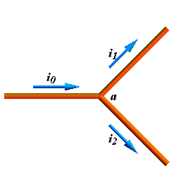
Junction Rule: The sum of current entering any junction is equal to the sum of current leaving that junction.
This rule we have derived in last chapter from conservation of charge argument.
![]()
Resistance in Parallel
Consider a circuit with three resistances ![]() ,
, ![]() ,
, ![]() in parallel.
in parallel.
Let us first consider the junction A (red dot). Current ![]() is entering the junction A and current
is entering the junction A and current ![]() and
and ![]() are leaving the junction. As per junction rule
are leaving the junction. As per junction rule
![]()
Now let us look at the junction B (blue dot). Current i is entering the junction B and current ![]() and
and ![]() are leaving the junction. As per junction rule
are leaving the junction. As per junction rule
![]()
By substituting the value of ![]() , in above equation we get
, in above equation we get
![]()
Potential difference across all the three resistor is V the potential difference across the battery.
As per Ohm's law, the potential difference across the three resistor is given as
![]()
Currents ![]() ,
, ![]() ,
, ![]() , can be now written in terms of corresponding resistances and applied potential difference V as
, can be now written in terms of corresponding resistances and applied potential difference V as

By substituting the values of ![]() ,
, ![]() , and
, and ![]() , in the total current equation we get
, in the total current equation we get


Or

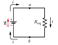
With similar logic if there are n resistors connected in parallel, we get equivalent resistors as

Checkpoint -5 (Multiloop circuit)
Three light bulbs of resistance 10 Ω each are arranged as shown in the circuit.
(a) With Switch-1 on, will the current ![]() and
and ![]() be same or different? Arrange the bulbs as per the brightness, higher first.
be same or different? Arrange the bulbs as per the brightness, higher first.
(b) With both Switch-1 and Switch-2 on, arrange the currents ![]() ,
, ![]() and
and ![]() in order of magnitude, higher first.
in order of magnitude, higher first.
(c) With both Switch-1 and Switch-2 on, arrange the bulbs as per their brightness with higher first.
Ammeter and Voltmeter
Ammeter
Ammeter is an instrument that measures current in a circuit loop.
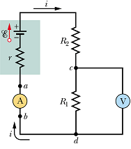
The current to be measured should passes through the meter. Therefore ammeter is always inserted in the loop.
Resistance ![]() of ammeter should be so low that it does not affect the loop current.
of ammeter should be so low that it does not affect the loop current.
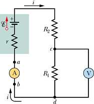
In the following circuit, ![]() and
and ![]() .
.
Voltmeter
Voltmeter is an instrument that measures potential difference across two points in a circuit.
Voltmeter is connected in parallel to the circuit element (resistance, capacitance, emf source etc.).
Voltmeter should not affect the loop current.
Voltmeter resistance ![]() should be much higher than the circuit element resistance.
should be much higher than the circuit element resistance.
In the following circuit, ![]() .
.
RC Circuits
Charging of Capacitor
Consider a circuit shown in the figure with uncharged capacitor.
Suppose at time t=0 s, the switch is flipped to the a position and the capacitor starts getting charged.
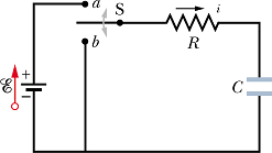
Suppose at any instant of time t, i is the current flowing through the loop and q is the charge on the capacitor C.
As per Kirchoff's loop rule we get
![]()
Here i R is potential difference across resistance R and ![]() is the potential difference across the capacitor.
is the potential difference across the capacitor.
Current Through the circuit is defined as

We can rewrite the equation as

Or

This is a linear differential equation. We can say that change in charge of a capacitor in time dt is given as

Total charge on the capacitor in time t will be sum of these incremental charges, we can compute it by integration.


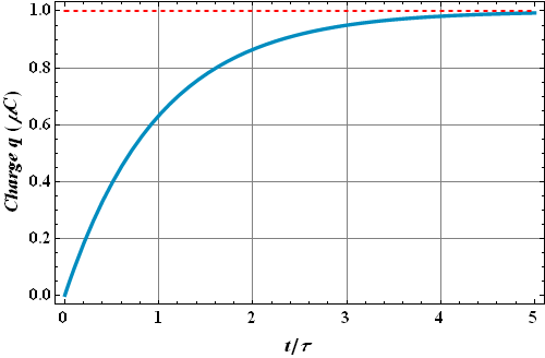
After solving this equation we get the charge at any time t
![]()
Or
![]()
Where τ = RC, is known as the "time constant" of the circuit.
EC is the maximum possible charge on the capacitor.
Ideally, capacitor will get fully charged in time t=∞ s.
In practice the capacitor will be charged to its 99.3% of its maximum charge in t=5τ.
Discharging of Capacitor
Now suppose the capacitor is charged and caries charge ![]() at time t=0 s, now the switch is flipped to the b position and the capacitor starts getting discharged.
at time t=0 s, now the switch is flipped to the b position and the capacitor starts getting discharged.
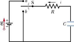
If i is the current flowing through the loop at any instant of time t and q is the charge on the capacitor C, as per Kirchoff's loop rule we get
![]()
Here ![]() is the potential difference across the capacitor. Now
is the potential difference across the capacitor. Now

We can rewrite the equation as

Or

Solution for this differential equation is
![]()
Ideally capacitor will get fully discharged in t=∞ s.
Practically capacitor will be left with 0.7% of its maximum charge in t=5τ.
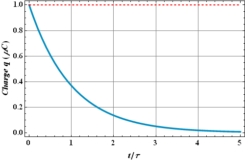
The current at any time is

If the capacitor was fully charged at t=0 s,  .
.
