Electromagnetic Oscillations and Alternating Current
Objectives
In this chapter we will learn about following topics.
How oscillations are produced in an LC circuit
How adding a resistance to a LC circuit makes the oscillations damped
What is an Alternating current (AC) source.
Learn about a phasor diagram.
How the AC current behaves in single element (R, L, or C) ac circuits.
Analysis of RLC circuit by phasor diagram.
Average power in AC circuits and how to maximize it.
Transmission looses in AC power delivery and how to improve it.
Transformers.
Electromagnetic oscillations in an LC circuit
LC Oscillations
Consider a circuit as shown in figure with a capacitor C and an inductor L.
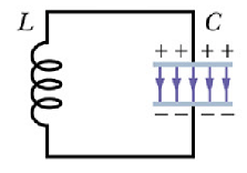
Suppose there was an initial charge q present on the capacitor. What happen when we short it with an inductor L?
The capacitor will discharge through the inductor and a time varying current i will build up in the inductor L.
If at any instant of time t there is a charge q on the capacitor and current i through the inductor, total energy U in the circuit can be given as

Where ![]() and
and ![]() are energy stored in electric and magnetic field respectively.
are energy stored in electric and magnetic field respectively.
If there is no loss of energy with time, then according to conservation of energy

Apply following formula to above equation

We get

Now current i through the circuit can also be written as

By substituting the value of i in our change in energy equation we get

Or

Since above equation is true for any value of i, therefore the term in brackets must be zero any time

Now again substitute the value of i=dq/dt, we get

We can rewrite above equation as

Does above equation looks familiar (Mathematically)?
Try to recollect equation describing the motion of a block on a spring (For simple harmonic motion acceleration is proportional to displacement with a negative sign)


Where ω is the angular frequency of the simple harmonic oscillator (spring block system)
Mathematically LC circuit equation and simple harmonic oscillator equation are same.
We can say that the charge in a LC circuit will oscillate with angular frequency ω such that

Where f is the frequency of oscillation. Charge on the capacitor at any time t will be given as
![]()
Where φ is the initial phase angle. Similarly current i through the inductor will be given as
![]()
Time period of these oscillations will be given as

Time variation of energy ![]() and
and ![]()
Let us see how energy ![]() and
and ![]() change in this circuit.
change in this circuit.


By plugging the value of ![]() in above equation we get
in above equation we get

A plot of total energy U, ![]() and
and ![]() is shown below.
is shown below.
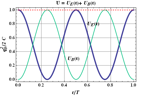
You can see that at T/4 ,3T/4 time, electric field energy goes to zero (Minimum) and current goes to its maximum value.
This is only true for an isolated LC circuit. In practical situation any LC circuit can get coupled with outside world and start transferring its energy to other inductors in the neighbor hood.
Checkpoint 1
A capacitor in an isolated LC oscillator has a maximum potential difference of 17 V and a maximum energy of 160 μJ. When the capacitor has a potential difference of 5 V and an energy of 10 μJ, what are (a) the emf across the inductor and (b) the energy stored in the magnetic field?
Hint:
Total energy is conserved. The potential difference across L and C should always be same.
Damped Oscillations in RLC Circuit:
If we add a resistor to the LC circuit as shown in figure.

When ever the current will flow through the circuit, some energy will be dissipated in the resistor. The rate of dissipation of energy is given as

Now the total rate of change of energy equation can be rewritten as

Or

By dividing both sides with i and substituting the value of i=dq/dt, we get


If you look it carefully, mathematically this is similar to the damped harmonic oscillator equation

This equation has the solution
![]()
Where

Similarly for damped oscillation of charge in a LRC circuit can be given as
![]()
Where

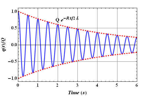
This equation describes oscillation of charge or current in the circuit with decaying amplitude ![]() .
.
Damped angular frequency ω' is always smaller than the undamped angular frequency ω.
the energy stored in the capacitor
the energy stored in the inductor
the energy stored in the current flowing in the circuit
the sum of the energy stored in the capacitor and that in the inductor
the energy dissipated in the circuit
The charge on the capacitor is equal to zero coulombs.
Charge is moving through the inductor.
The energy is equally shared between the electric and magnetic fields.
The energy in the electric field is maximized.
The energy in the magnetic field is maximized.
ω = LC
ω = √LC
ω = 1/√LC
ω = 1/(LC)
ω = 2π/√LC
increase the inductance
increase the emf
increase in both inductance and capacitance
increase the capacitance
increase the circuit resistance
Alternating current (AC) circuits
Direct Current (dc.)
A battery emf E always generates a current that has a constant direction. This type of current is known as "direct current or dc".
Alternating Current (ac.)
We are familiar with the device shown in following figure.
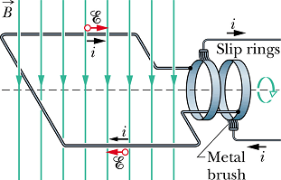
This is a different type of emf generating source. The emf E produced by such a source is given as
![]()
Where A is the area of the generator loop, N is the number of loops or windings, ω is the angular frequency of rotation and B is the magnetic field.
In this type of device (generator) emf E change direction with a frequency 2π f=ω. In US f=60 Hz.
Because the emf E change direction, therefore current i through the connected circuit will also change direction with frequency f. Such type of current is known as "alternating current or ac."
Symbol for an alternating current source is shown in the following figure.
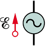
Symbol convention :
To analyze ac circuits, we will use the following symbol convention.
Lower case letter will be used to indicate instantaneous value of an ac quantity (like current i etc.)
Upper case letters will be used to indicate constant amplitude of ac quantities.
Example, ac current i will be written as
![]()
Symbol i is for instantaneous value of current and I is its maximum value.
Phasors
A convenient method of representing ac quantities like ![]() and
and ![]() is a phasor diagram.
is a phasor diagram.
In phasor diagram, the ac quantities like ![]() and
and ![]() are represented by a rotating vector known as phasor using the following conventions.
are represented by a rotating vector known as phasor using the following conventions.
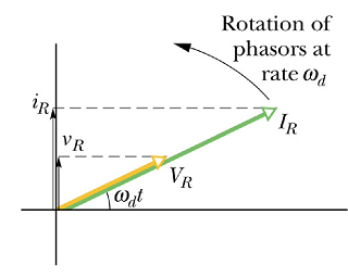
Phasor rotate in counterclockwise direction with angular speed ω.
The length of phasor is proportional to the amplitude of the ac quantity.
Projection of the phasor on vertical axis (y-component) gives the instantaneous value of the ac quantity.
Rotation angle ω t for each phasor is called the phase of the quantity.
Three Simple Circuits
Our objective is to analyze a RLC circuit connected to an ac emf source.
Analysis of an RLC circuit becomes simple and easy if we can analyze three individual elements (R, C, and L) connected to an ac emf source.
A Resistive load :
Let us consider a resistance R connected to an ac generator.
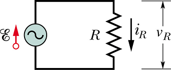
According to Kirchhoff s law we have
![]()
The current ![]() through the resistance will be given as
through the resistance will be given as

The amplitude of ![]() is given as
is given as

The voltage ![]() across R is
across R is
![]()
The relation between voltage and current amplitude is
![]()
Variation of ![]() and
and ![]() as a function of time (Resistive load)
as a function of time (Resistive load)
It can be seen that both ![]() and
and ![]() reach to their respective maximum and minimum values at the same time.
reach to their respective maximum and minimum values at the same time.
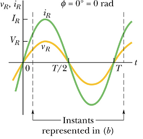
For a resistive load ![]() and
and ![]() are always in phase.
are always in phase.
Phasor diagram of a resistive load
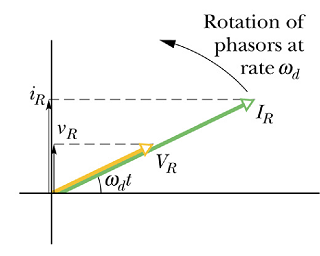
In this phasor diagram the phase of ![]() and
and ![]() is same at any instant.
is same at any instant.
Phasor ![]() and
and ![]() always points in the same direction at any instant of time.
always points in the same direction at any instant of time.
By convention ![]() is written as
is written as
![]()
Voltage ![]() is written as
is written as
![]()
For a resistor, the initial phase angle ![]() .
.
Average Power in a resistive load
As we have seen that in an ac circuit, the current ![]() and voltage
and voltage ![]() across R are changing with time, therefore dissipated power P(t) is a function of time.
across R are changing with time, therefore dissipated power P(t) is a function of time.
To estimate dissipated power in the resistor we have to calculate average power <P> in one cycle or in one time period T.

By substituting the values of ![]() and
and ![]() we get.
we get.

Now

Therefore average power dissipated in a resistive load R in an ac circuit is given as

To make the equation look same as in the dc case, a new quantity called "root mean square" voltage ![]() is defined
is defined

Now the dissipated average power <P> in a resistive load can be written as

Similarly "root mean square" current is defined as ![]()

Checkpoint 2
If we increase the driving frequency in a circuit with a purely resistive load, do (a) amplitude ![]() and (b) amplitude
and (b) amplitude ![]() increase, decrease, or remain the same?
increase, decrease, or remain the same?
Hint: Amplitude ![]() is related to amplitude
is related to amplitude ![]() and
and ![]() .
.
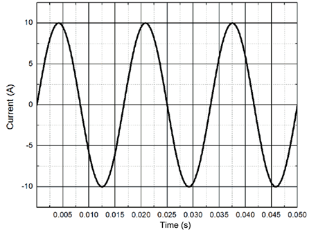
24 Ω
21 Ω
17 Ω
14 Ω
12 Ω
A Capacitive Load
Connect an ac emf source to a capacitor C.
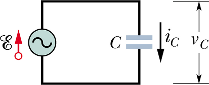
If at a given instant ![]() is the potential difference across the capacitor, then according to Kirchhoff s law
is the potential difference across the capacitor, then according to Kirchhoff s law
![]()
The charge ![]() on the capacitor at any instant is given as
on the capacitor at any instant is given as
![]()
The current ![]() through the circuit at any instant is given as
through the circuit at any instant is given as

Above equation can also be written as
![]()
Amplitude of voltage ![]() across the capacitor is equal to amplitude of applied emf
across the capacitor is equal to amplitude of applied emf ![]() .
. ![]() , therefore the current amplitude is
, therefore the current amplitude is

This convention is followed to make this equation look similar to resistive load. The quantity ![]() is called "Capacitive reactance or Capacitive impedance". The current through such a circuit can be written as
is called "Capacitive reactance or Capacitive impedance". The current through such a circuit can be written as

You can see that current ![]() through a capacitive load is
through a capacitive load is ![]() out of phase with respect to voltage across the capacitor.
out of phase with respect to voltage across the capacitor.
If we write ![]() as
as

The phase angle ![]() for a capacitor.
for a capacitor.
In complex number notation "capacitive reactance" is written as

Here ![]() is "iota". In complex number notation
is "iota". In complex number notation ![]() can also be written as
can also be written as
Capacitive impedance decreases with increase in capacitance and angular frequency ω
![]()
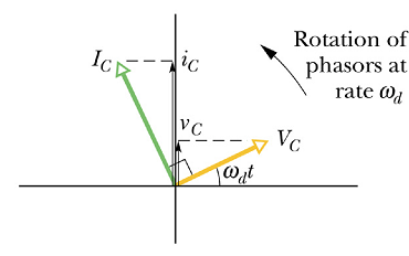
Current in a capacitor leads the voltage by π/2 phase.

In terms of phasor diagram, the current and voltage across a capacitor connected to an ac source, at any instant is shown below.
Average Power in a capacitive load
Power P(t) dissipated in the capacitor at any instant is given as
![]()
By using the trigonometric relation
![]()
we get

Average dissipated power <P> in the capacitor can be calculated as below

This shows that a capacitor does not dissipate any power on the average.
In some part of the cycle it absorbs the power and store it as electric field energy, in the other part of the cycle it gives it back to the circuit.
In the end on the average no power is used by a capacitive load in an ac circuit.
Checkpoint 3
The figure shows, in (a), a sine curve ![]() and three other sinusoidal curves A(t), B(t), and C(t), each of the form
and three other sinusoidal curves A(t), B(t), and C(t), each of the form ![]() . (a) Rank the three other curves according to the value of φ, most positive first and most negative last. (b) Which curve corresponds to which phasor in figure-b? (c) Which curve leads the others?
. (a) Rank the three other curves according to the value of φ, most positive first and most negative last. (b) Which curve corresponds to which phasor in figure-b? (c) Which curve leads the others?
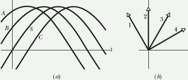
Hint: Remember if one sin curve looks ahead of the other sin curve, it means it is lagging behind the other. In phasor diagram net positive phase goes in counter clockwise direction.

C has the largest rms current and A has the smallest.
A has the largest rms current and C has the smallest.
B has the largest rms current and A has the smallest.
B has the largest rms current and C has the smallest.
C has the largest rms current and B has the smallest.
An Inductive Load
Connect an ac emf source to an Inductor L.
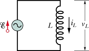
The voltage ![]() across the inductor L at any instant is related to change in current
across the inductor L at any instant is related to change in current ![]() through the circuit.
through the circuit.

According to Kirchhoff s law we have

Or


Above equation can also be written as

Amplitude of voltage ![]() across the inductor is
across the inductor is ![]() .
.
The current amplitude is

The quantity ![]() is called "Inductive reactance or Inductive impedance".
is called "Inductive reactance or Inductive impedance".
You can see that current ![]() through an inductive load is
through an inductive load is ![]() out of phase with respect to voltage across the inductor.
out of phase with respect to voltage across the inductor.
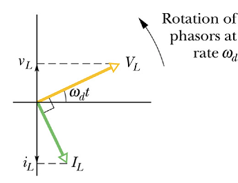
In other words the current in an inductor lags behind the voltage by π/2 phase.
If we write ![]() as
as

The phase angle ![]() for an inductor.
for an inductor.
In complex number notation "Inductive reactance" is written as
![]()
Inductive impedance Increases with increase in inductance and angular frequency ω
In complex number notation ![]() is written as
is written as

-i means -π/2 phase difference.
Current in an inductor lags behind the voltage by π/2 phase.
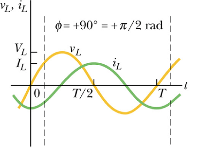
In terms of phasor diagram, the current and voltage across an inductor connected to an ac source, at any instant is shown below.
Average Power in an inductive load
Power P(t) dissipated in the inductor at any instant is given as
![]()
Again by using the trigonometric relation
![]()
we get

Average dissipated power <P> in the inductor can be calculated as below

This shows that an inductor does not dissipate any power on the average.
In some part of the cycle it absorbs the power and store it as magnetic field energy, in the other part of the cycle it gives it back to the circuit.
In the end on the average no power is used by an inductive load in an ac circuit.
Checkpoint 4
If we increase the driving frequency in a circuit with a purely capacitive load, do (a) amplitude ![]() and (b) amplitude
and (b) amplitude ![]() increase, decrease, or remain the same? If, instead, the circuit has a purely inductive load, do (c) amplitude
increase, decrease, or remain the same? If, instead, the circuit has a purely inductive load, do (c) amplitude ![]() and (d) amplitude
and (d) amplitude ![]() increase, decrease, or remain the same?
increase, decrease, or remain the same?
Hint: Voltage across the terminals of the load will always be equal to voltage across the emf source. Capacitive reactance ![]() . Inductive reactance is
. Inductive reactance is ![]() . Magnitude of current I=V/X.
. Magnitude of current I=V/X.
0.040 H
0.080 H
0.16 H
0.32 H
0.64 H
Resonance in RLC circuits
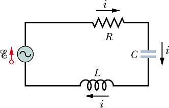
Connect an ac emf source E to a RLC circuit.
![]()
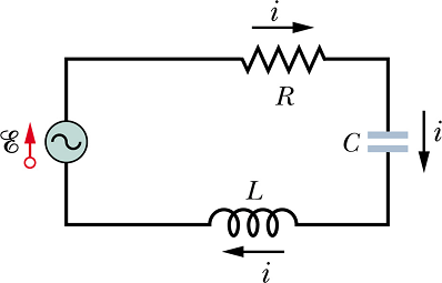
Since R, L and C are in series, same current i should flow through all the elements. Let us assume that the current through the circuit is
![]()
If we draw the phasor vector for current I at any instant of time, we can draw the phasor vectors of ![]() for resistor R,
for resistor R, ![]() for inductor L and
for inductor L and ![]() for capacitor C.
for capacitor C.
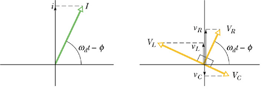
![]() is in phase with the current phasor vector.
is in phase with the current phasor vector.
![]() is
is ![]() ahead of the current phasor vector.
ahead of the current phasor vector.
![]() is
is ![]() behind the current phasor vector.
behind the current phasor vector.
From the loop rule the emf E at any time t is the sum of voltages ![]() ,
, ![]() and
and ![]() .
.
![]()
In a loop, at any time current ![]() through all the loads is same, therefore
through all the loads is same, therefore
![]()
By substituting value of ![]() and
and ![]() we get.
we get.

Here Z is the complex impedance of the RLC circuit.

Magnitude and phase of impedance can be given as


Current through such a RLC circuit will have φ phase difference with applied emf.

On phaser diagram, emf E is the sin component (projection on vertical axis) of the phasor vector ![]() . when sin component of a phasor is the sum of sin components
. when sin component of a phasor is the sum of sin components ![]() ,
, ![]() and
and ![]() of other phasors. That implies that the phasor
of other phasors. That implies that the phasor ![]() is the phasor (vector) sum of three phasors
is the phasor (vector) sum of three phasors ![]() ,
, ![]() and
and ![]() .
.
Since ![]() and
and ![]() are opposite to each other, we can combine these two phasors as
are opposite to each other, we can combine these two phasors as ![]() . Now
. Now ![]() is the phasor sum of
is the phasor sum of ![]() and
and ![]() .
.
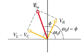
By applying Pythagoras theorem to above phasor diagram, we get
![]()
In terms of current I and reactance ![]() ,
, ![]() and resistance R, we can rewrite the above equation as
and resistance R, we can rewrite the above equation as
![]()
From above equation we get the value of current amplitude I.

Denominator is called the impedance Z of the circuit for the driving angular frequency ![]() .
.
![]()
We can write

Or

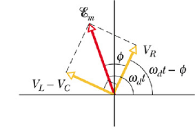
Similarly above diagram can be used to calculate the phase constant

There can be three possibilities :
![]() , implies phase angle φ>0. Current phasor lags behind the emf phasor. Circuit is more inductive.
, implies phase angle φ>0. Current phasor lags behind the emf phasor. Circuit is more inductive.
If ![]() , implies phase angle φ<0. Current phasor leads the emf phasor. Circuit is more capacitive.
, implies phase angle φ<0. Current phasor leads the emf phasor. Circuit is more capacitive.
If ![]() , implies phase angle φ=0. Current phasor and emf phasor are in phase.
, implies phase angle φ=0. Current phasor and emf phasor are in phase.
Resonance
Let us look at the current amplitude equation.

For a given value of R, the current amplitude will be maximum when

Or

We can say that the current through a RLC circuit for a given value of R will be maximum when the natural angular frequency ![]() is equal to the driving angular frequency of the emf source.
is equal to the driving angular frequency of the emf source.

This condition is called resonance condition.
In other words we can state that in a RLC circuit when inductive reactance ![]() is equal to the capacitive reactance, the circuit is in resonance condition and maximum current flows through the circuit.
is equal to the capacitive reactance, the circuit is in resonance condition and maximum current flows through the circuit.
How can we achieve resonance?
By changing the inductance L of the circuit such that ![]() .
.
By changing the capacitance C of the circuit such that ![]() .
.
By changing the driving angular frequency ![]() of emf source such that
of emf source such that ![]() .
.
Variation of current amplitude in a RLC circuit.
Variation of current phase in a RLC circuit.
Checkpoint 4
Here are the capacitive reactance and inductive reactance, respectively, for three sinusoidally driven series RLC circuits: (1) 50 Ω, 100 Ω; (2) 50 Ω, 50 Ω;(3) 100 Ω, 50 Ω. (a) For each, does the current lead or lag the applied emf, or are the two in phase? (b) Which circuit is in resonance?
Hint: If ![]() , φ is negative. If
, φ is negative. If ![]() , φ is positive. Resonance condition is
, φ is positive. Resonance condition is ![]() .
.
resistor
capacitor
inductor
light bulb
Power in AC circuits
Let us now calculate average power dissipated or used by a RLC circuit. We know that average power is dissipated only in the resistance R of the circuit. Instantaneous power P(t) dissipated in a R of circuit is given as
![]()
Average of ![]() is 1/2, therefore average power <P> dissipated in a RLC circuit is
is 1/2, therefore average power <P> dissipated in a RLC circuit is

We can write it in terms of root-mean-square, or rms current ![]() term
term

In a RLC circuit, ![]() is related to rms value of emf amplitude
is related to rms value of emf amplitude ![]() and impedance Z.
and impedance Z.

Now average power <P> dissipated is given as

If we look at the phase diagram of RLC circuit, the ratio R/Z is equal to the cosine of phase φ.
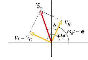

<P> is given as
![]()
Term Cos(φ) is called power factor.
To maximize the transmitted power in a RLC circuit, value of Cos(φ) should be one, or the phase angle φ should be as close to zero as possible.
If a circuit is highly inductive, it can be made less by reducing the capacitance value in the circuit or putting a capacitance in series as that will reduce the equivalent capacitance in the circuit.
To achieve maximum power transmission, power companies place series connected capacitors throughout their transmission systems.
Checkpoint 5
(a) If the current in a sinusoidally driven series RLC circuit leads the emf, would we increase or decrease the capacitance to increase the rate at which energy is supplied to the resistance? (b) Would this change bring the resonant angular frequency of the circuit closer to the angular frequency of the emf or put it farther away?
Hint: If current leads the emf, φ is negative, implies ![]() . It means we need to reduce the value of
. It means we need to reduce the value of ![]() Resonance condition is
Resonance condition is ![]() .
.
Transformers, AC power transmission
Energy Transmission Requirements
Average power delivered by a power station of rms emf ![]() with power factor Cos(φ)=1, is
with power factor Cos(φ)=1, is
![]()
The power dissipated ![]() in the transmission lines of resistance R will be given as
in the transmission lines of resistance R will be given as
![]()
Power delivered by a power station is constant, it can be seen that the rms current ![]() , will increase if we reduce the rms emf
, will increase if we reduce the rms emf ![]() .
.
The increase in ![]() will cause increase in transmission power loss
will cause increase in transmission power loss ![]() .
.
Problem 1
Typical resistance for a transmission line is 0.220Ω/km. Power station delivered 350 MW power on a 1000 km transmission line. (a) If the rms emf ![]() , what percentage of total power is lost in the transmission line? (b) If we reduce the rms emf to 375 kV, what percentage of power will be lost in the transmission line?
, what percentage of total power is lost in the transmission line? (b) If we reduce the rms emf to 375 kV, what percentage of power will be lost in the transmission line?
Solution :
For a 1000 km transmission line R=220Ω.
(a) When ![]() ,
, ![]() will be given as
will be given as
![]() ,
, ![]() in Amperes is
in Amperes is

![]()
![]() in Watts is
in Watts is
![]()
![]()
Percentage loss is
![]()
![]()
(b) When ![]() ,
, ![]() in Amperes is
in Amperes is

![]()
![]() in Watts is
in Watts is
![]()
![]()
Percentage loss is
![]()
![]()
You can see just by doubling the ![]() , the transmission losses increases from 14% to 55%.
, the transmission losses increases from 14% to 55%.
The Ideal Transformer:
Reduction in transmission loss requires high voltage.
Safe operations at home require low voltage.
To achieve this we use a device called Transformer.
Transformer is a device that can change the voltage amplitude of an ac emf source.
It consists of two coils wound on an iron core. The coil on which ac emf source is connected is called "primary core".
The core which delivers emf to the circuit is called "secondary coil".
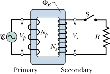
If ![]() is the emf amplitude on the primary side and
is the emf amplitude on the primary side and ![]() is the emf amplitude on the secondary side, in an ideal transformer, the ratio of two is related to the number of turns
is the emf amplitude on the secondary side, in an ideal transformer, the ratio of two is related to the number of turns ![]() of primary coil and number of turns
of primary coil and number of turns ![]() of secondary coil.
of secondary coil.

Or

When ![]() the transformer is called "step down transformer". In this transformer
the transformer is called "step down transformer". In this transformer ![]() .
.
When ![]() the transformer is called "step up transformer". In this transformer
the transformer is called "step up transformer". In this transformer ![]() .
.
Current in primary coils :
Current through secondary coil induce an emf in primary which affects the current in primary coil.
Estimation of current in primary coil by taking all kind of inductions into account can be involved but by conservation of energy argument, we can find it more easily.
If R is the load in secondary loop, the power ![]() dissipated in secondary loop should be
dissipated in secondary loop should be

If ![]() is the current in primary coil, power
is the current in primary coil, power ![]() delivered by primary circuit is
delivered by primary circuit is
![]()
As per conservation of energy, the power dissipated in secondary loop should be equal to the power ![]() delivered by primary circuit.
delivered by primary circuit.

Or

By rewriting above equation we get the value of primary loop current ![]() .
.

When R is the load in secondary circuit of a transformer, It is equivalent to say that primary coil is connected to a load ![]() . Where equivalent load
. Where equivalent load ![]() is given as
is given as

Impedance Matching :
Any emf source (dc or ac) delivers maximum power to a load, when the value of load is equal to the internal resistance (for a dc source) or internal impedance (for an ac source).
Checkpoint 6
An alternating-current emf device in a certain circuit has a smaller resistance than that of the resistive load in the circuit; to increase the transfer of energy from the device to the load, a transformer will be connected between the two. (a) Should ![]() be greater than or less than
be greater than or less than ![]() ? (b) Will that make it a step-up or step-down transformer?
? (b) Will that make it a step-up or step-down transformer?
Hint: For maximum delivery of energy, equivalent resistance ![]() should be equal to the internal resistance of the emf source.
should be equal to the internal resistance of the emf source.
