Current and Resistance
Objectives
In this chapter we will introduce the following concepts
Electric current (symbol i).
Electric current density vector (symbol ![]() ).
).
Drift speed (symbol ![]() ).
).
Resistance (symbol R).
Resistivity (symbol ρ).
Ohmic and non - Ohmic conductors.
We will also cover the following topics
Ohm's Law.
Power in electric Circuit.
What is Electric Current?
Consider a loop of a conductor (copper).
The free electrons (conduction electrons) are in random motion in this conductor.
Consider a hypothetical plane intersecting the wire at any location.
Conduction electrons pass through this imaginary plane in both directions —therefore there is no net transport of charges through the imaginary plane thus no current through the wire.
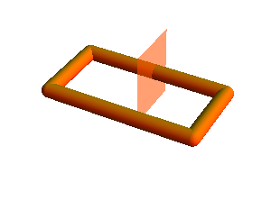
Now make a break in the conductor and insert a battery.
Potential difference between the two points is generated which cause the conduction electrons to move from negative terminal to positive terminal.
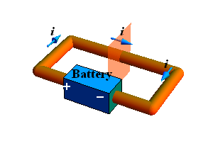
Now there is net flow of conduction electrons through any imaginary plane intersecting the conductor in one direction —therefore there is a net transport of charges through this plane thus there is current through the wire.
Electric current i through a conductor is defined as net charge crossing any imaginary plane intersecting (cross section of ) the conductor in unit time.
If Δq charge cross in time Δt, the current i is defined as

Current is a scalar quantity
SI units for current are Coulombs/second = Ampere.
Current Direction
Electric current is represented by an arrow (although it is a scalar quantity).
If the flowing charge carriers are positive, the direction of current is along velocity ![]() of charges.
of charges.
If the flowing charge carriers are negative the direction of current is opposite to velocity ![]() of charges.
of charges.
A current arrow is drawn in the direction in which positive charge carriers would move, even if the actual charge carriers are negative and move in the opposite direction.
Current and Charge Conservation :
When a conductor is connected to a battery, and a steady current is flowing through it. The current flowing through any imaginary plane intersecting the conductor will be same.
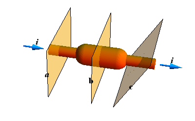
In the above conductor, the number of charge carriers entering from the left sides of plane a, b and c are same as the number of charge carriers leaving on their right hand sides.
Consider a conductor splitting into two parts
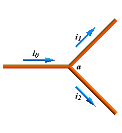
In this conductor current entering the junction point a is ![]() while leaving point a is
while leaving point a is ![]() .
.
Since no charges are created at point a, therefore
![]()
Checkpoint 1
The figure here shows a portion of a circuit. What are the magnitude and direction of the current i in the lower right-hand wire?
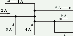
Hint: In steady state total current entering a point is equal to total current leaving a point.
Current density ![]()
Consider a conductor of cross sectional area A.
Current is the total charges intersecting any imaginary plane in the conductor in unit time.
Turn on the current (press play) and note how many charges cross the plane "A"?
We noticed that all the charges (blue color) with in length L cross the plane "A".
If t is the time taken by all charges (q), with in length L, to cross the plane "A", the current through the conductor will be
![]()
Let us calculate total charge q with in length "L" of the conductor.
If n is the free charge density in the conductor, then the total charges in length L of the conductor will be
![]()
Where e is the charge on each electron, therefore current through the conductor is

We noticed that each charge moves distance L in time t, therefore magnitude of the velocity ![]() of each charge will be
of each charge will be

![]() is called drift velocity and now current through the conductor can also be written in terms of drift velocity.
is called drift velocity and now current through the conductor can also be written in terms of drift velocity.

Relation between Current and Current density
Some time we are interested in just the net current through a conductor, but in certain situation we may be interested in the net flow of charge through a cross sectional area of a conductor at a particular point. This can be achieved by using current density ![]() at any point.
at any point.
Current density ![]() at any point in the conductor is defined as
at any point in the conductor is defined as
![]()
Current density ![]() is a vector quantity.
is a vector quantity.
Current i is the flux of current density ![]() through a cross section area
through a cross section area ![]() of the conductor at any point.
of the conductor at any point.

When current density ![]() is uniform and is parallel to the cross section area
is uniform and is parallel to the cross section area ![]() of a conductor, the current at all the points in conductor will be given as
of a conductor, the current at all the points in conductor will be given as
![]()
SI Units for current density will be ![]()
Checkpoint 2
The figure shows conduction electrons moving leftward in a wire. Are the following quantities leftward or rightward: (a) the current i, (b) the current density ![]() , (c) the electric field
, (c) the electric field ![]() in the wire?
in the wire?
Problem - 1 (Current density)
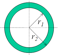
The magnitude J of the current density in a certain wire with a circular cross section of radius R=3.50 mm is given by ![]() , with J in amperes per square meter and radial distance r in meters. What is the current through the outer section bounded by r=0.520R and r=R?
, with J in amperes per square meter and radial distance r in meters. What is the current through the outer section bounded by r=0.520R and r=R?
Current through any wire of cross section A is given as.

Here ![]() is parallel to the area
is parallel to the area ![]() . If we consider a small ring of radius r and width dr, the area dA=2π r dr, The current through a ring of inner radius
. If we consider a small ring of radius r and width dr, the area dA=2π r dr, The current through a ring of inner radius ![]() and outer radius
and outer radius ![]() can be given as
can be given as

![]()
Value of Current can be computed by substituting the values of ![]() and
and ![]() .
.
![]()
![]()
Resistance and Resistivity
Resistance:
When we apply a potential difference (voltage) V across a conductor, current i flows through the conductor.
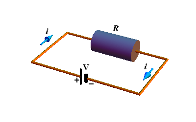
The conductor resistance R is defined as the ratio of potential difference V to current i.

SI Units for resistance are ohm with symbol Ω.
![]()
Symbol of a resistance
![]()
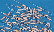
Resistor: A conductor whose function is to provide a specific resistance to a circuit is called a resistor.
Resistivity
Unlike electrostatic case, the electric field in a conductor is non zero when a battery is connected across the conductor.
We define resistivity ρ of a material as

In vector form
![]()
SI Units for resistivity is 
Resistance is the property of an object, Resistivity is the property of a material.
Example: We can define resistance of a particular copper wire, but resistivity is defined for material copper
Conductivity
Conductivity σ of a material is an other term which is defined as

In vector form
![]()
SI Units for conductivity is ![]()
Calculating Resistance from Resistivity
Consider a conductor of length L and area of cross section A, When we apply potential difference V across its two ends, current i flow through it.
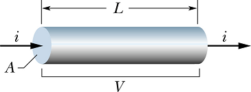
The electric field E in the conductor is given as

The current density in the conductor is given as
![]()
From the value of J and E we can calculate the resistivity of the material

From above equation we obtained the relation between the resistivity ρ and resistance R.

Checkpoint 3
The figure here shows three cylindrical copper conductors along with their face areas and lengths. Rank them according to the current through them, greatest first, when the same potential difference V is placed across their lengths.

Hint: All are made up of copper therefore have same resistivity.

Current through a conducting object for same applied potential difference V is

Variation of Resistivity with temperature.
Following is the curve of resistivity of a material (say copper) as a function of temperature
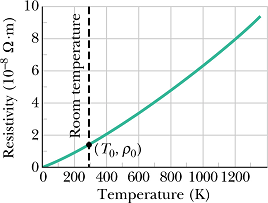
It can be seen that the variation of resistivity ρ with temperature is more or less linear.
For many practical purposes, following empirical formula is used.
![]()
Where ![]() is the reference temperature, usually room temperature is taken as reference
is the reference temperature, usually room temperature is taken as reference ![]() K.
K. ![]() is the resistivity at the reference temperature
is the resistivity at the reference temperature ![]() .
.
For copper ![]() Ω·m.
Ω·m.
Since we only measure temperature difference ![]() , therefore it does not matter whether we use Celsius or Kelvin scale.
, therefore it does not matter whether we use Celsius or Kelvin scale.
α is called temperature coefficient of resistivity, it is chosen so that it gives a good agreement with experimental result.
Problem - 2 (Resistivity/Resistance)
Two conductors are made of the same material and have the same length. Conductor A is a solid wire of diameter 1.0 mm. Conductor B is a hollow tube of outside diameter 2.0 mm and inside diameter 1.0 mm. What is the resistance ratio ![]() , measured between their ends?
, measured between their ends?
Since both the objects are made up of same material, their resistivity ρ will be same.
Resistance of an object is a function of resistivity ρ, cross section area A and length of the object L.

For the first object area is ![]()
For second object (hollow cylinder) the cross section area ![]()
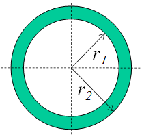
Now the value of ![]() and
and ![]() can be computed with same length L of the objects.
can be computed with same length L of the objects.
![]()

![]()

The ratio ![]() can be computed
can be computed
![]()

By substituting the values of r, ![]() and
and ![]() we can get the ratio
we can get the ratio
![]()
![]()
Ohm's Law
In reality, Ohm' s law is not a law. Due to historic reasons, it is called law.
According to Ohm' s law the current i through a conductor is proportional to the potential difference V applied across the conductor.

![]()
The proportionality constant is called the resistance R of the conductor.

If we plot current i through a conductor as a function of applied potential V we call it a V-i curve and it is a linear plot.
V-i plot of a conductor following Ohm's law is shown in the figure
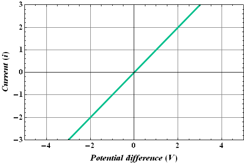
Such conductors are called Ohmic conductors.
A conductor behaves as an Ohmic conductor, when the resistance of the device is independent of the magnitude and polarity of the applied potential difference.
Non - Ohmic Conductors
There are conductors which do not follow Ohm' s law.
One example is a semiconductor diode.
The V-i curve of such a conductor is not linear and is shown below.
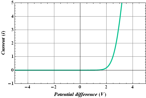
These conductors are known as non - Ohmic conductors.
Checkpoint 4
The following table gives the current i (in amperes) through two devices for several values of potential difference V (in volts). From these data, determine which device does not obey Ohm's law.
| Device | 1 | Device | 2 |
| V | i | V | i |
| 2.00 | 4.50 | 2.00 | 1.50 |
| 3.00 | 6.75 | 3.00 | 2.20 |
| 4.00 | 9.00 | 4.00 | 2.80 |
Hint: If the device obeys Ohm's law, the ratio of ![]() should be same for each observation.
should be same for each observation.

Microscopic View of Ohm's Law
In a conductor, free electrons move randomly with an effective speed ![]() (for copper
(for copper ![]() .
.
During this random motion these electrons undergo collisions with stationary atoms (gray doted line in the figure).
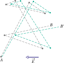
When an electric field is applied, these electrons experience a force ![]() in the direction opposite to the direction of electric field
in the direction opposite to the direction of electric field
![]()
The force gives rise to acceleration ![]() to the electrons for free time between two successive collisions.
to the electrons for free time between two successive collisions.

Where ![]() is the mass of an electron. This acceleration will produce a drift velocity
is the mass of an electron. This acceleration will produce a drift velocity ![]() .
.
If τ is the average free time between two successive collisions, the magnitude of ![]() (for copper
(for copper ![]() ) can be given as
) can be given as

Once we know the drift velocity of the electrons and density n of free electrons in a conductor we can calculate current density J.

Electric field is related to the current density as
![]()
Comparing two equations giving the value of current density, we get

Or
![]()
The resistivity ρ is a function of electron charge e, electron mass ![]() , free electron density n and average free time τ (mean free time).
, free electron density n and average free time τ (mean free time).
Resistivity ρ does not depend upon the applied electric field. It is a material property. This is exactly what Ohm's law state.
Problem - 3 (Ohm's Law)
A human being can be electrocuted if a current as small as 50 mA passes near the heart. An electrician working with sweaty hands makes good contact with the two conductors he is holding. If his resistance is 2000Ω, what might the fatal voltage be? [Answer: 100 V].
If V is the potential difference across a conductor, as per ohm's law

![]()
![]()
![]()
Power in Electric Circuits
Consider a circuit with a battery maintaining potential difference V across the terminals a and b of a device.
The device could be a motor, a lamp or any resistor.
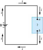
Potential ![]() at terminal a is greater than potential
at terminal a is greater than potential ![]() at terminal b. Therefore potential difference ΔV across the terminal is negative
at terminal b. Therefore potential difference ΔV across the terminal is negative
![]()
Where V is the potential difference across the battery.
When a charge dq moves across these terminals in time dt, the change in potential energy dU will be
![]()
Negative change in potential energy means it is decreasing.
Conservation of energy dictates that this energy is going to some other source.
This other source is nothing but the device connected in the circuit.
In other words we can say the energy is being used by the device.
Change in energy dE of the device will be given as
![]()
This energy is delivered by the circuit to the device in time dt, as per definition of power the power P delivered by the battery to the device.

The power delivered by a battery to any device is given as P=i V
If the device is a resistance R, the power delivered can be written as
![]()
Or

In a resistive load or device, the delivered energy gets converted into heat.
SI Units for power are Ampere * Volt = Watt, Symbol "W"

Checkpoint 5
A potential difference V is connected across a device with resistance R, causing current i through the device. Rank the following variations according to the change in the rate at which electrical energy is converted to thermal energy due to the resistance, greatest change first: (a) V is doubled with R unchanged, (b) i is doubled with R unchanged, (c) R is doubled with V unchanged, (d) R is doubled with i unchanged.
Hint: The power delivered to a resistive load is given as.

Problem - 4 (Electric Power)
Thermal energy is developed in a resistor at a rate of 130 W when the current is 4.00 A. What is the resistance?
Rate of developed thermal energy in a resistance is the power delivered by the battery.
![]()


![]()
